Motivation

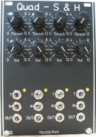
This is a analog Quad Sample and Hold build around the LF398, as many others. The trigger and signal inputs are normalled and has individual attenuators. So you can have four differing outputs from the same input signal. You can easily adapt the timing to your needs with changing two capacitors per channel. You can have four differently timed Sample and Hold in one module.
Specs and features
- Quad Sample and Hold
- DC coupled
- Trigger/Gate input with LED
- Trigger/Gate inputs normalled
- Attenuator for each input
- Signal inputs normalled
- Trigger/Gate Threshold
- Runs on +/-12V and +/-15V
- Power consumption below 50mA each rail
Implementation
Schematic

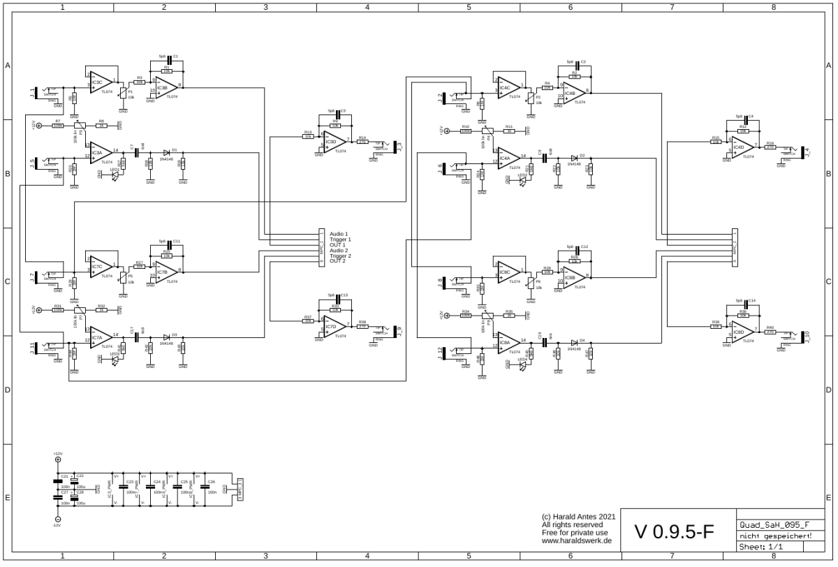
Quad Sample and Hold: Schematic control board

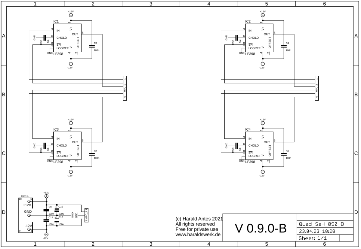
Quad Sample and Hold: Schematic main board
Description:
Build around the LF398. Have a look at the data sheet. The rising edge of the incoming signal to the trigger input generates a pulse to start the sample. This is done with a comparator. The trigger level is set with a potentiometer.
You can adapt the the timing to your needs. As in every analog Sample and Hold the timing here is a compromise between sample speed and droop. To change the sample time change the capacitor behind the comparator. To change the hold time (acceptable droop) change the hold capacitor at pin 6 of the LF398. You have for Sample and Holds here. So you can implement different timings.
Calibration
- None
Building hints
- None
Special parts
- None
Download
Quad Sample and Hold control board documentation downloadQuad Sample and Hold control board Gerber files download
Quad Sample and Hold main board documentation download
Quad Sample and Hold main board Gerber files download
Quad Sample and Hold *.fpd file