Motivation
This module was originally build for my Shakuhachi to Synth project to provide the start/stop pulse for the Pitch to voltage converter. But it turned out to be much more useful. When you have the basics for your synthesizer like VCO, VCF, VCA, ADSR, LFO,... and some controllers and you want more, then using your keyboard to steer the synthesizer it is time for some modules to produce trigger signals out of different sources. Here is one of them. A signal to trigger converter. You can feed in a changing signal and every time the signal went through zero, a trigger is generated dependent on the direction from where the zero point is crossed. You can add a threshold manually or CV controlled to move the zero point up or down as well. When the signal crosses zero from positive to negative a trigger of about 0.1msec is generated at output -Trig. When the signal crosses zero from negative to positive a trigger of about 0.1msec is generated at output +Trig. Output +/-Trig provides both triggers. This output can be used to generate interesting rhythmic patterns when the threshold is set by a slowly moving CV or some DC offset is applied to the signal.
Specs and features
- Threshold set manually and with CV
- Output for +Trig, -Trig and +/-Trig: 0.1msec
- Runs on +/-15V and +/-12V with minor resistor changes
- Power consumption below 25mA each rail
Implementation
Schematic

Signal to Trigger converter schematic: Control board

Signal to Trigger converter schematic: Main board
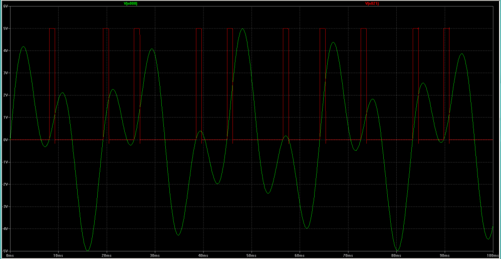
Example: Signal to trigger
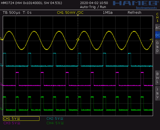
Screenshot: Sine to Trigger
The uppermost line (Yellow) shows the input signal. The second line (Blue) shows the trigger when the input signal moves to the positive site. The third line (Purple) shows the trigger when the input signal moves to the negative site. On the fourth line (Green) you can see both triggers added. This picture is taken without any threshold.
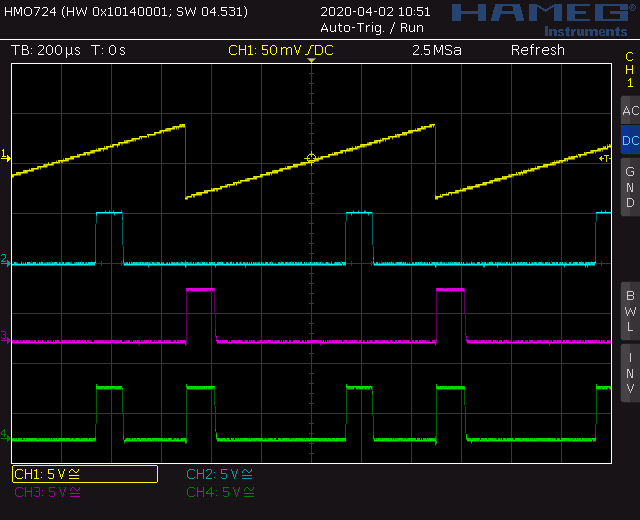
Screenshot: Saw to Trigger with threshold
The uppermost line (Yellow) shows the input signal. The second line (Blue) shows the trigger when the input signal moves to the positive site. The third line (Purple) shows the trigger when the input signal moves to the negative site. On the fourth line (Green) you can see both triggers added. Here you can easily see what is the threshold fore.
TopCalibration
- None
Building hints
- None
Special parts
- None
Download
Signal to trigger converter control board documentation downloadSignal to trigger converter control board Gerber files download
Signal to trigger converter main board documentation download
Signal to trigger converter main board Gerber files download
Signal to trigger converter *.fpd file
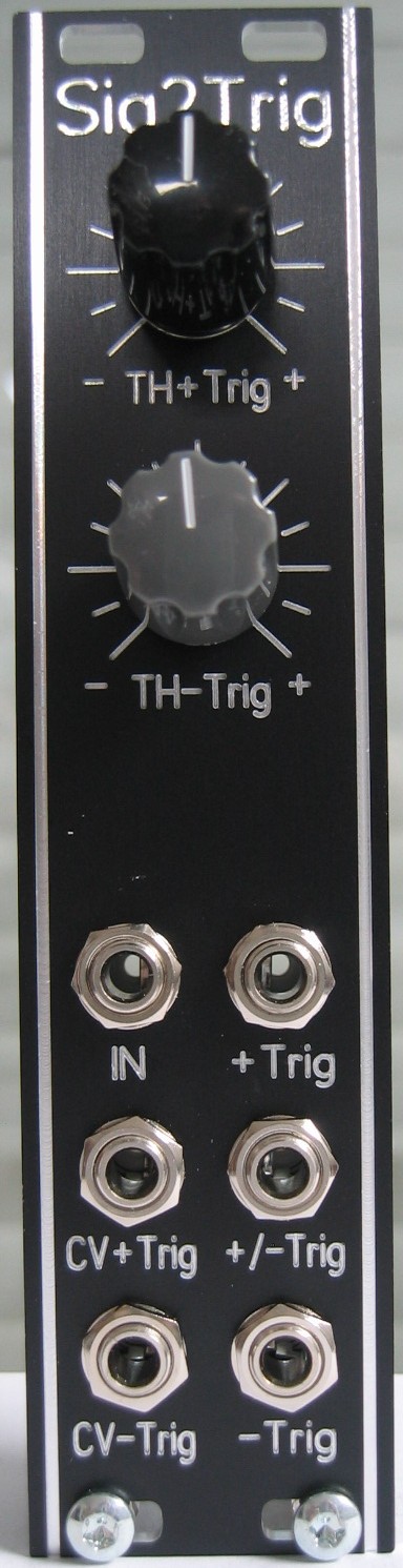
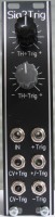
Signal to trigger converter: Front view
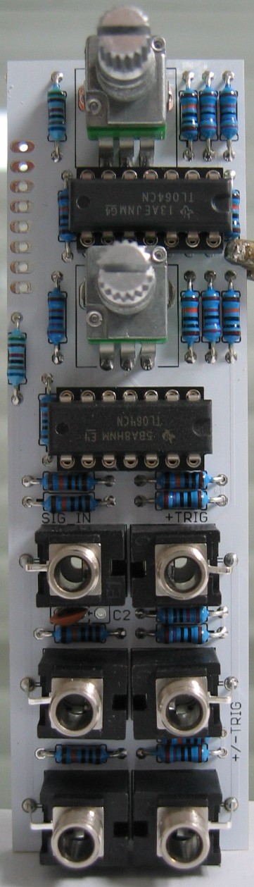
Signal to trigger converter: Populated control PCB
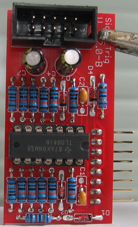
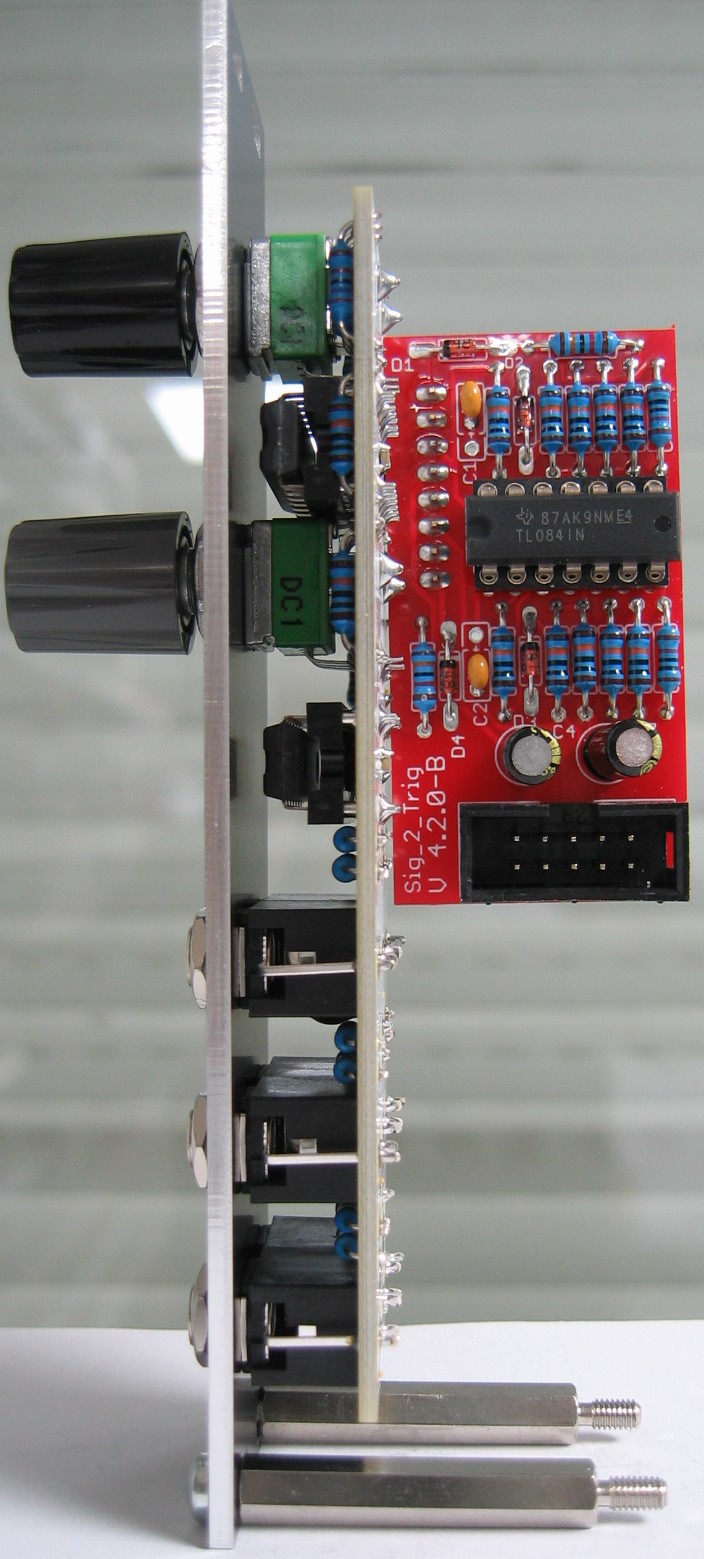
Signal to trigger converter: Populated main PCB
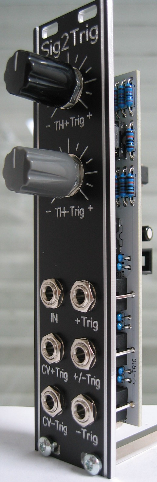
Signal to trigger converter: Half front view
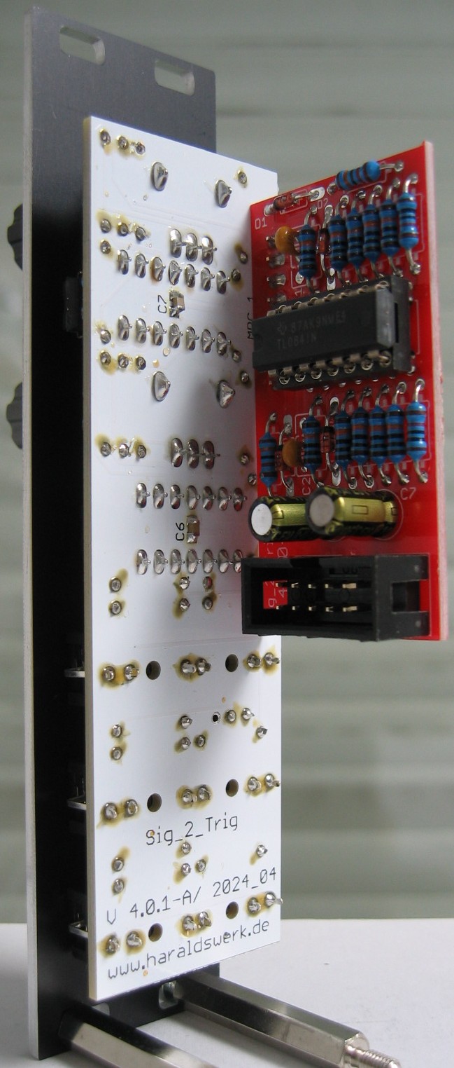
Signal to trigger converter: Half back view