Motivation
Sometimes you need a PSU with very low ripple. With a common voltage regulator this can be achieved by some additional filtering. Here I use a LM350 with an additional RC filter before the smoothing capacitors and a capacitor in the regulation path of the LM350.
The drawback of this schematic is increased power consumption. The resistors in the RC input filter get rather hot under heavy load. Use 2W (minimum) or higher rated resistors and mount them with some distance to the PCB. You should keep the load under 2A. You can drive heavier loads, but watch for the temperature of the resistors. You can find more details in “Small signal audio design” second edition from Douglas Self in chapter 25 p713ff.
Specs and features
Implementation
Schematic

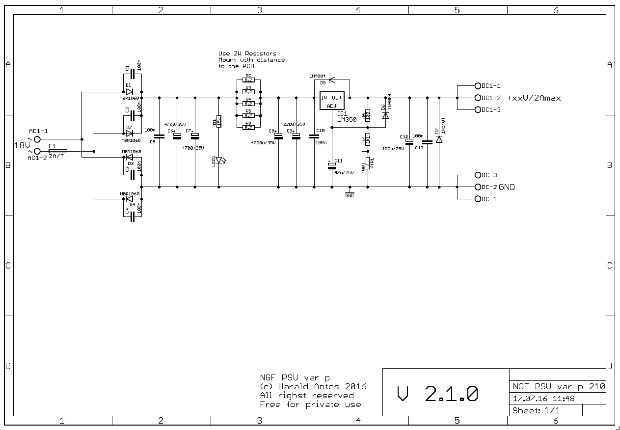
Ultra low ripple PSU with LM350. Schematic
Description:
After the rectifier diodes C6 and C7 are the reservoir capacitors followed by the RC filter build of R2; R3, R4, R8 and C8, C9. D5 serves as protection diode for reverse biasing the voltage regulator. R6, R7, TR1 serves as voltage divider to adjust the output voltage to15V. The 1.2V reference voltage between ADJ and out is amplified about 12times to make a 15V output. So is the noise and ripple. C11 between ADJ pin and GND reduces noise and ripple considerably. Protective diode D6 is needed to safely discharge C11 if the output is short-circuited. D7 protects against short-circuited when you daisy chain two PSU for a +/- PSU if one of the outputs is short circuited. With the above measures the ripple is down in the noise floor..
Calibration
- Adjust the output voltage with TR1
Special parts
- The resistors in the RC input filter get rather hot under heavy load. Use 2W (minimum) or higher rated resistors and mount them with some distance to the PCB.