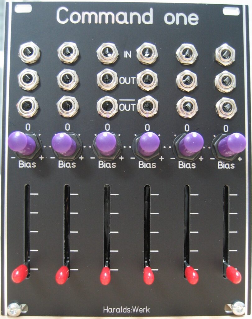
This utility module gives you a wide range of variable and adjustable control voltages from -10V to +10V. This only depends on the knob and slider setting and patching within itself. If used with external input it can attenuate and offset the incoming signal. I use this module for steering modules which lacks of attenuator at the inputs or in greater patches for applying control voltages to far away modules. It is quite comfortable to have the controls in the first row of your case and not somewhere in the messy patch hardly in reach for your hands
Specs and features
Variable and adjustable control voltages from -10V to +10V
Six independent active attenuator with external signals
Positive and negative offset for external signals
Runs on +/-12V and +/-15V
Power consumption below 20mA each rail
The documentation and the Gerber files for download can be found in my website.
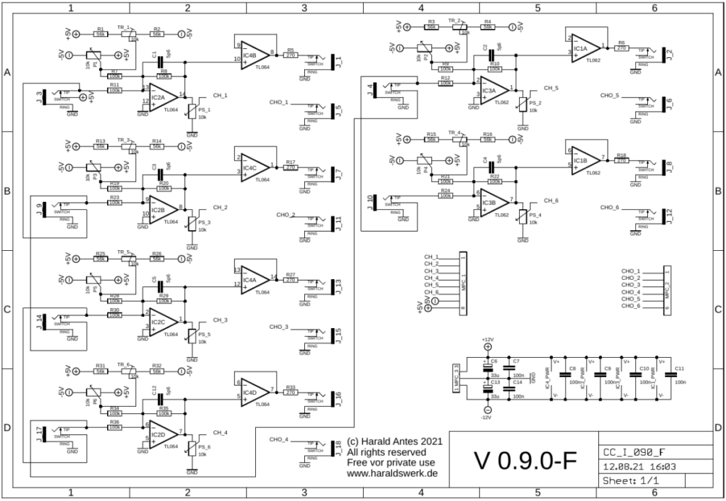
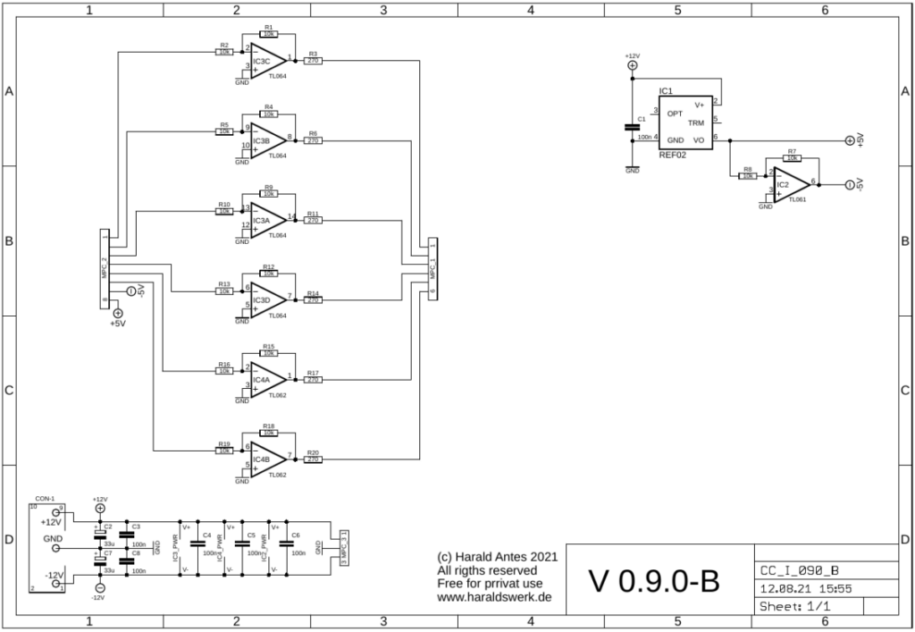
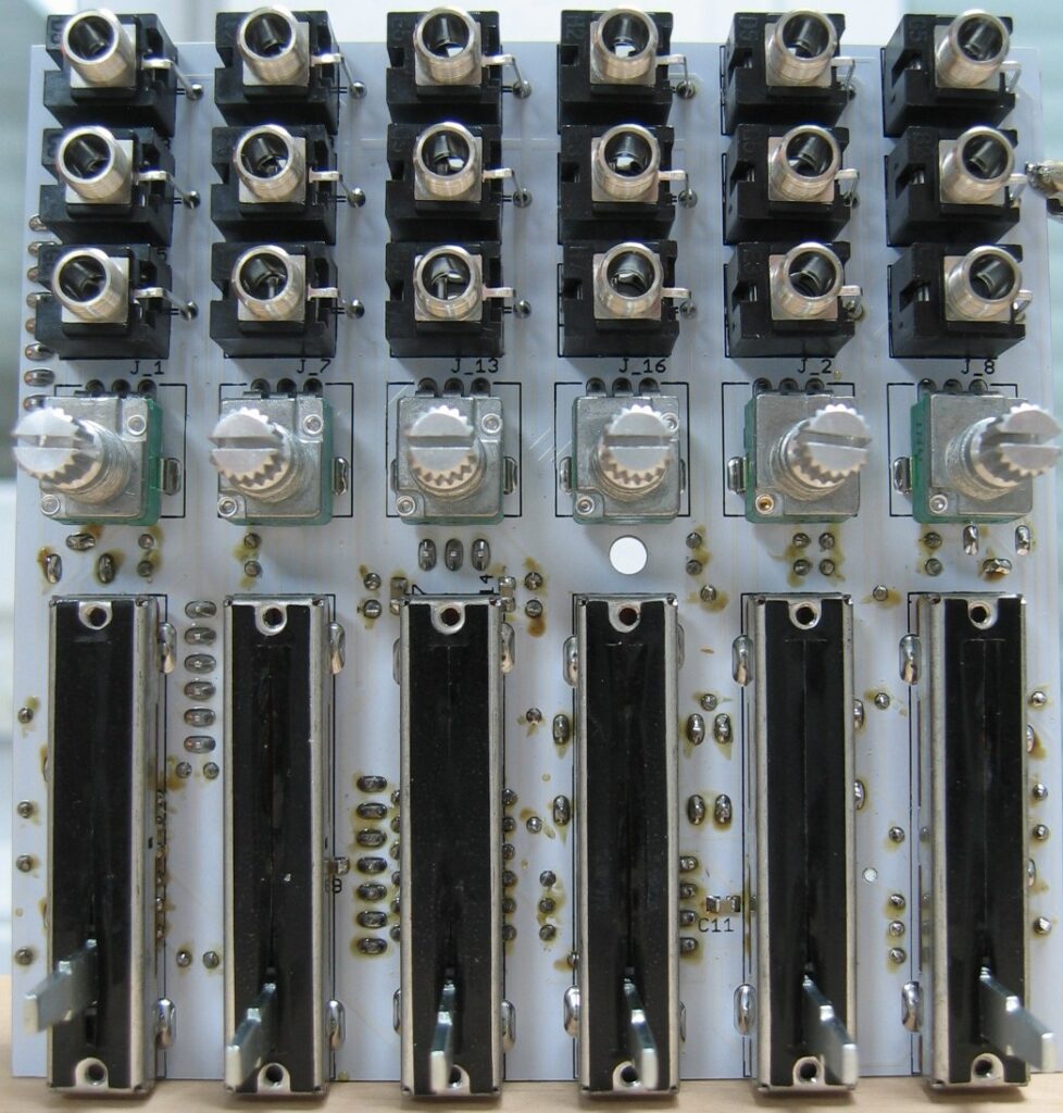
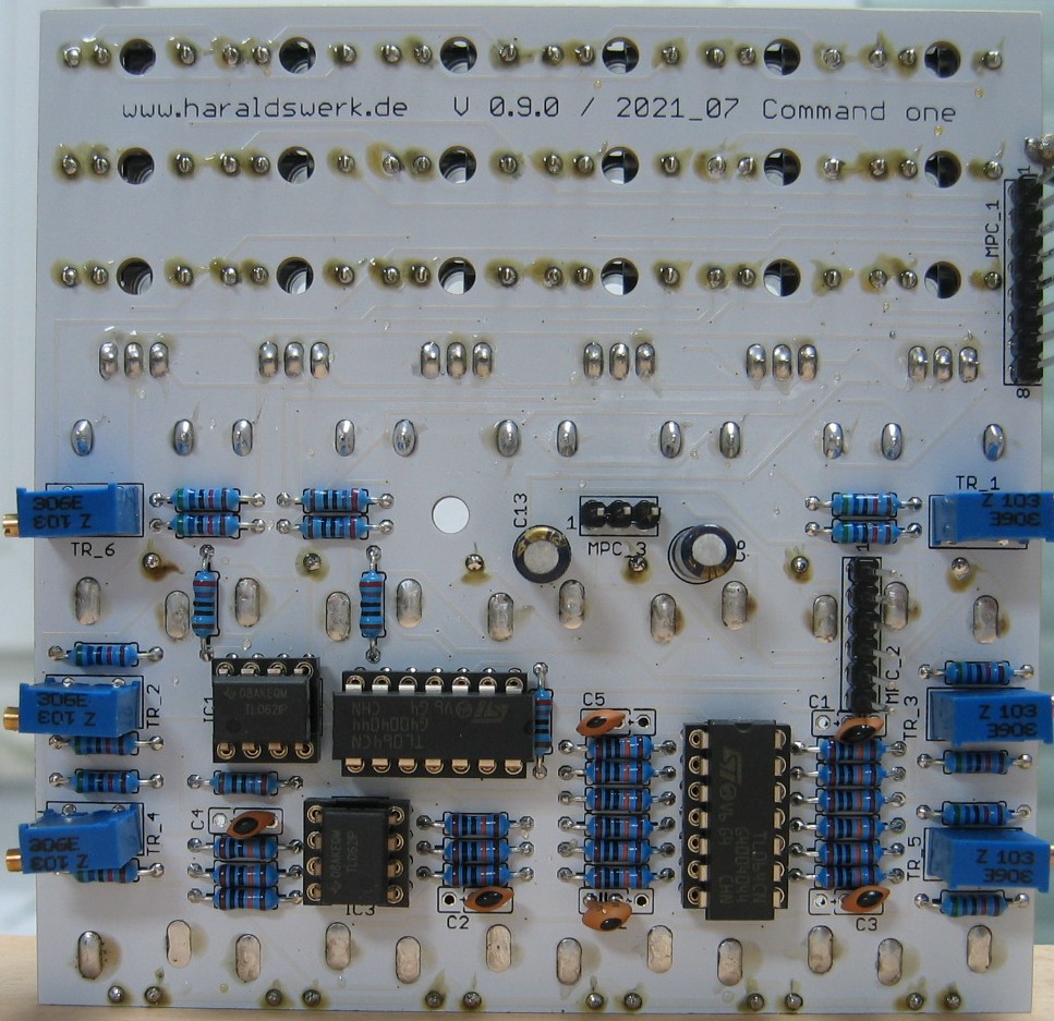
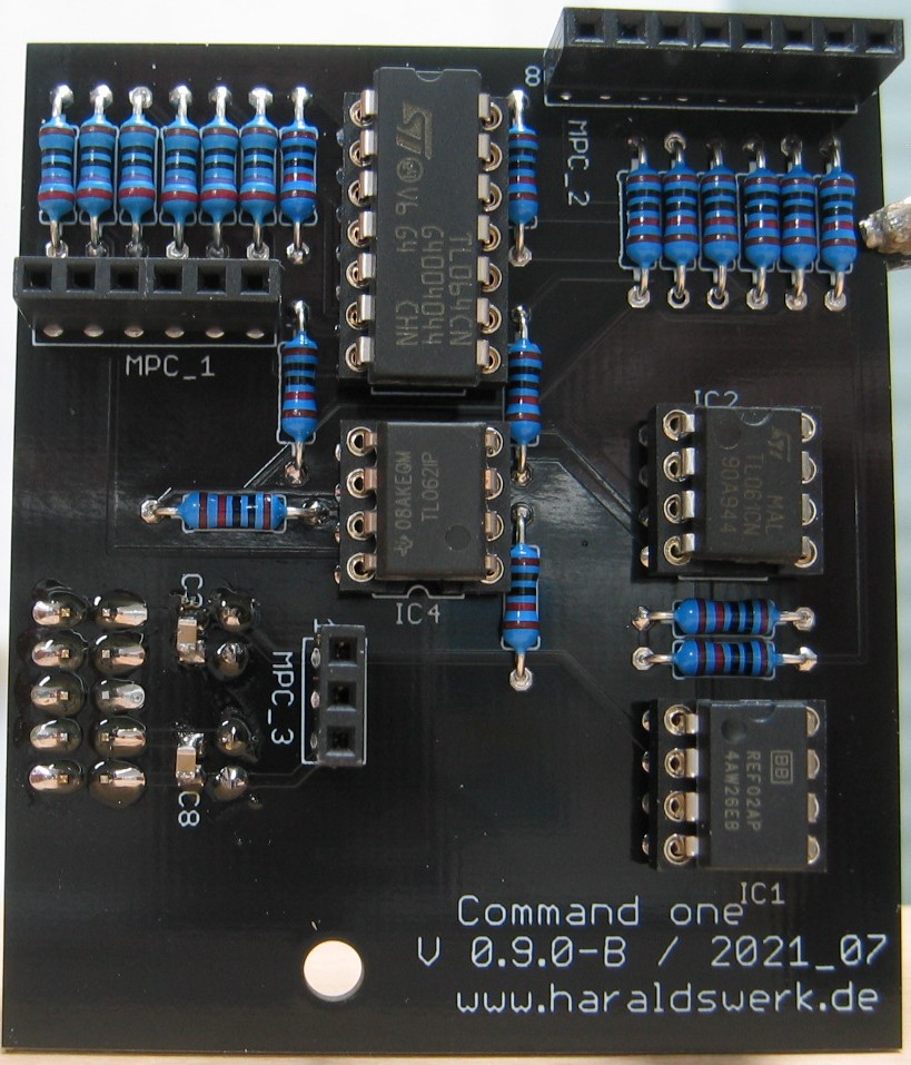
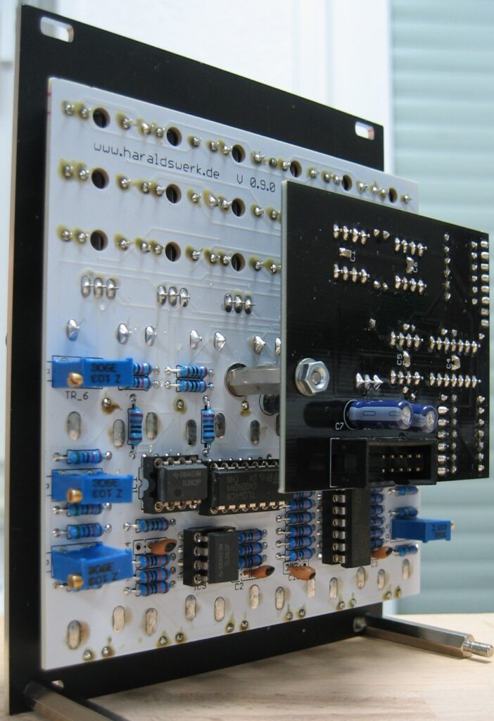
Command one: Schematic control boardCommand one: Schematic main boardCommand one: Populated control PCB Command one: Populated control PCB back Command one: Populated main PCBCommand one: Back viewCommand one: Side view
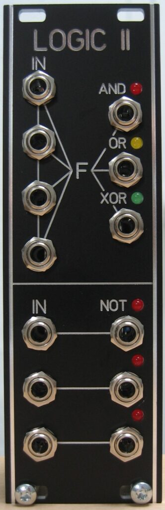
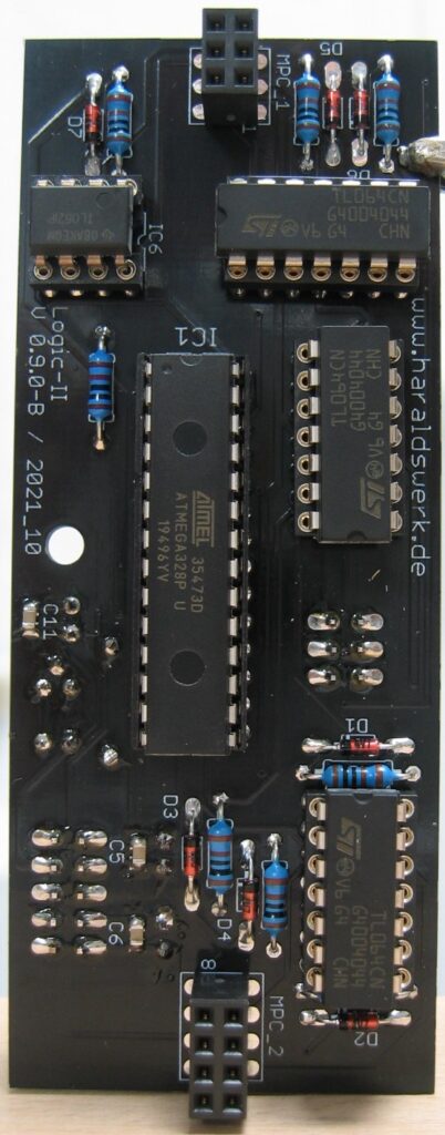
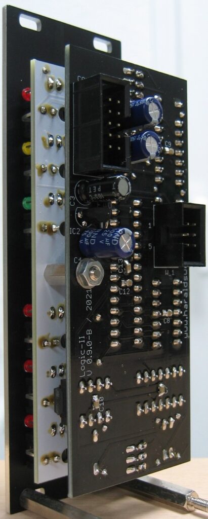
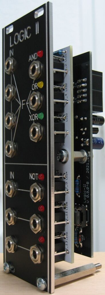
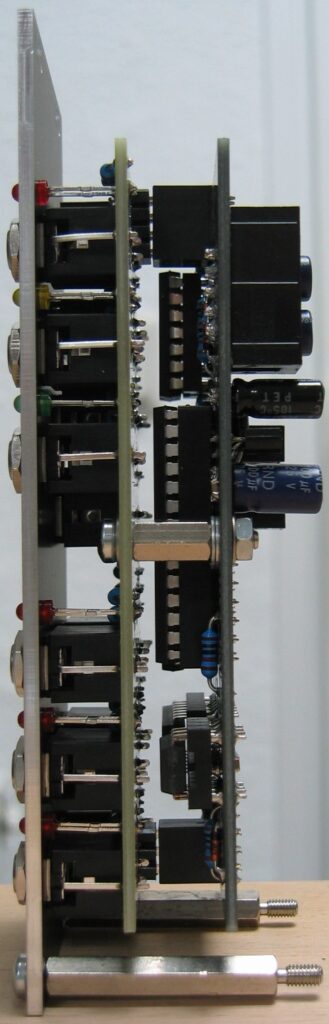
This logic module takes up to four input signals and outputs the logic function AND, OR, XOR dependent on the input signals. The inputs are normalized so you can use less then the four inputs. It has three NOT functions as well.
Specs and features
Up to four input signals
AND, OR, XOR parallel out
Three NOT functions
Runs on +/-12V and +/-15V
Power consumption below 30mA positive rail. 5mA negative rail.
The documentation and the Gerber files for download can be found in my website.
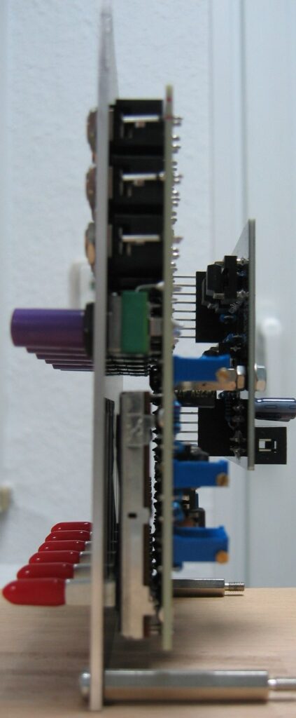
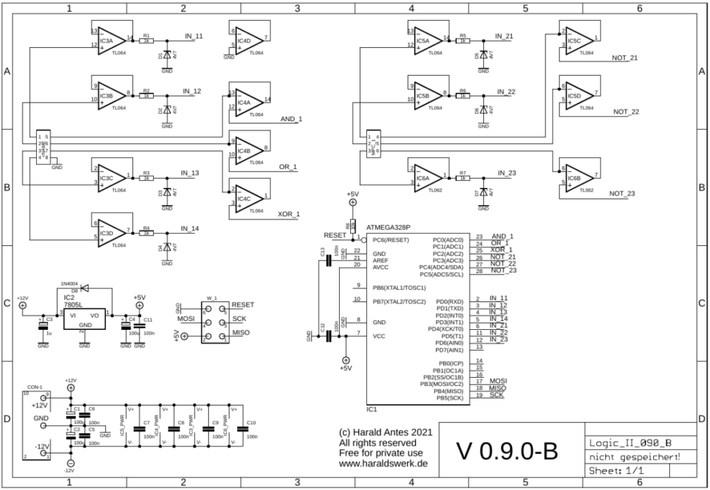
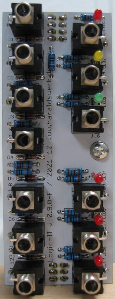
Logic II: Control board schematicLogic II: Main board schematicLogic II: Populated control boardLogic II: Populated main boardLogic II: Back viewLogic II: Half front viewLogic II: Side view
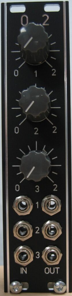
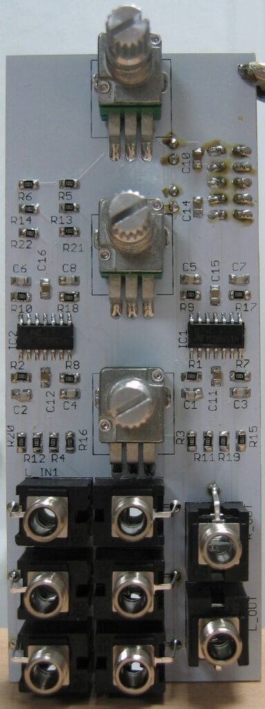
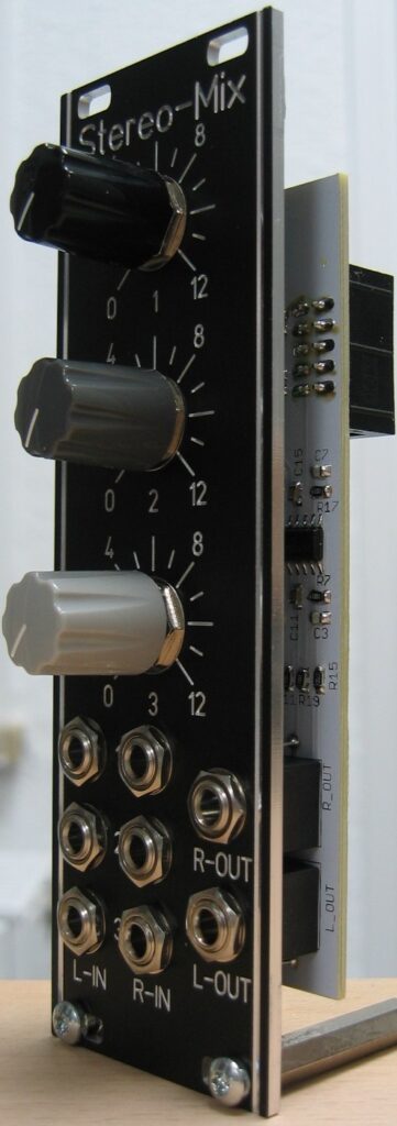
While working with modulars I have had some modules lacking input attenuator or output volume. To cure that I have build this module. It is usable as active attenuator and / or amplifier. The attenuation or amplification is determined by one resistor per channel, so you can easily adjust the attenuation or amplification to your needs.
Specs and features
Three independent active attenuator or amplifier
Attenuation / amplification adjusted with one resistor.
Runs on +/-12V and +/-15V
Power consumption below 20mA each rail
The documentation and the Gerber files for download can be found in my website.
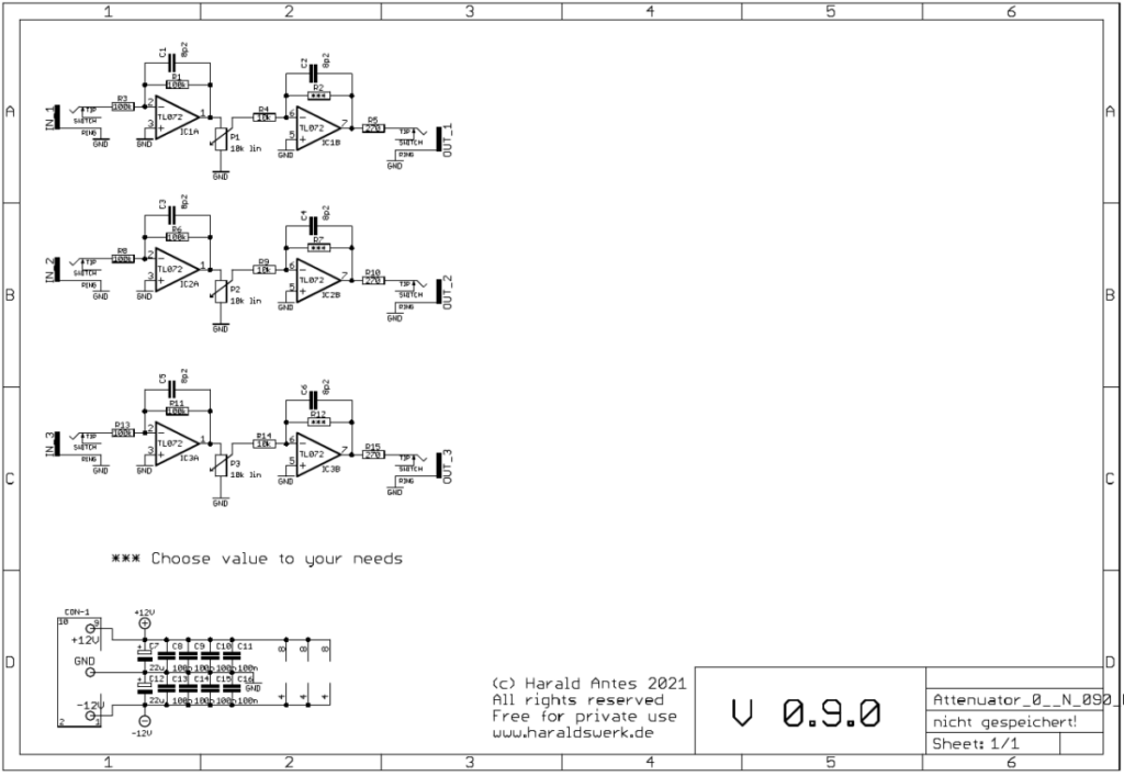
Attenuator / Amplifier 0..N: Schematic
The attenuation or amplification is determined by one resistor per Channel (R2, R7, R12)
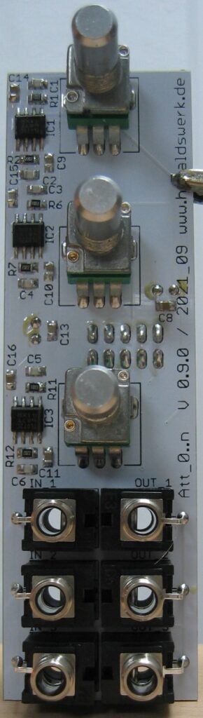
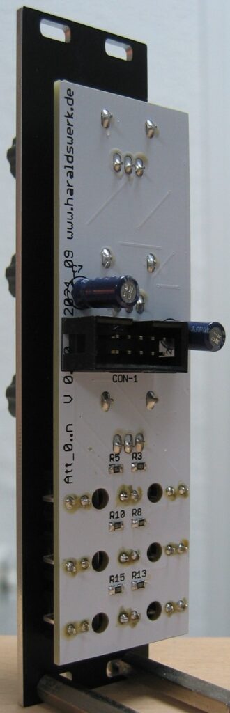
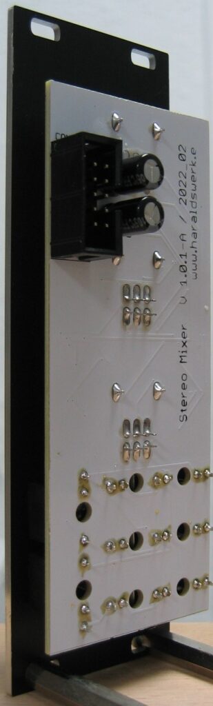
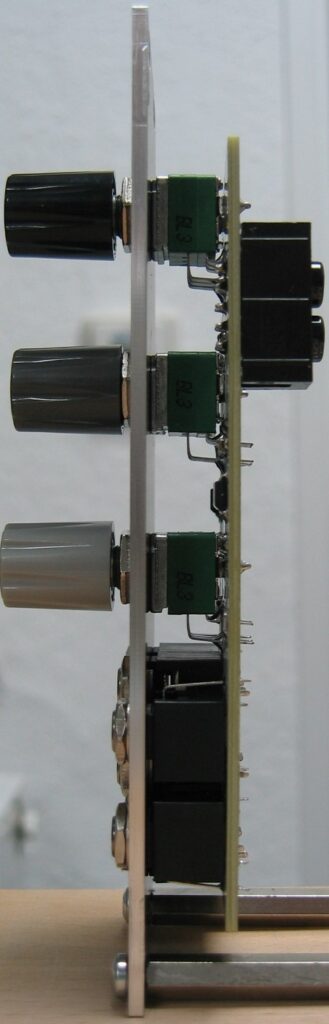
Attenuator / Amplifier 0..N: Populated PCBAttenuator / Amplifier 0..N: Back viewAttenuator / Amplifier 0..N: Side view
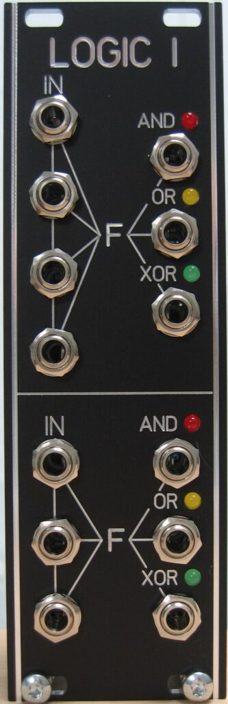
This logic module takes up to four input signals and outputs the logic function AND, OR, XOR dependent on the input signals. The inputs are normalized so you can use less then the four inputs.
Specs and features
Up to four input signals
AND, OR, XOR parallel out
Runs on +/-12V and +/-15V
Power consumption below 30mA positive rail. 5mA negative rail.
The documentation and the Gerber files for download can be found in my website.
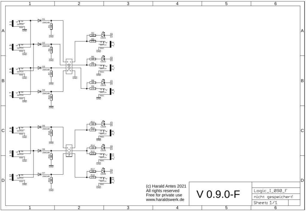
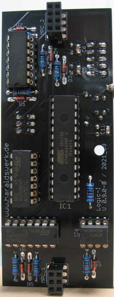
Logic I: Schematic control boardLogic I: Schematic main board
Nothing special to mention. On page one you see the input and outputs. On page two are the input protection circuitry, the microprocessor and the output buffers. The logic is done in software.
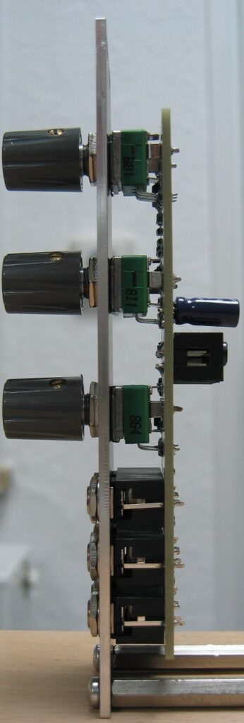
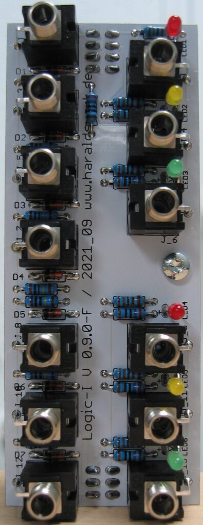
Logic I: Populated control boardLogic I: Populated main boardLogic I: Back viewLogic I: Side view
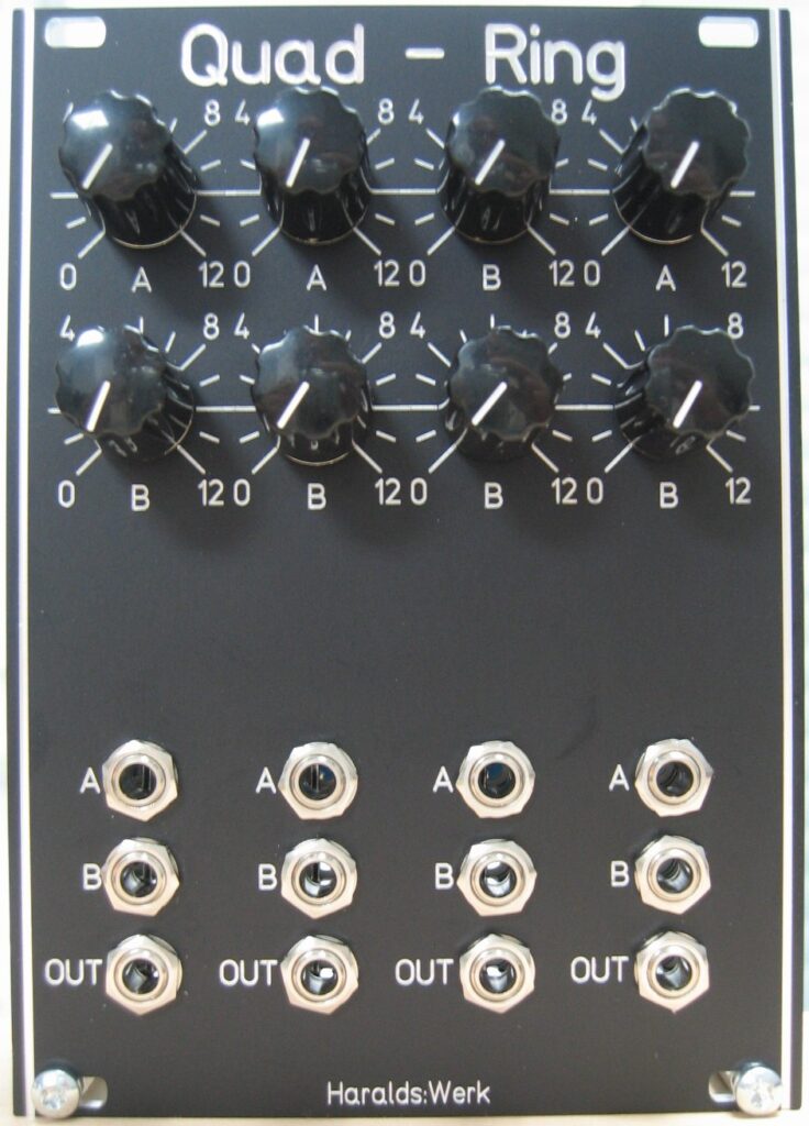
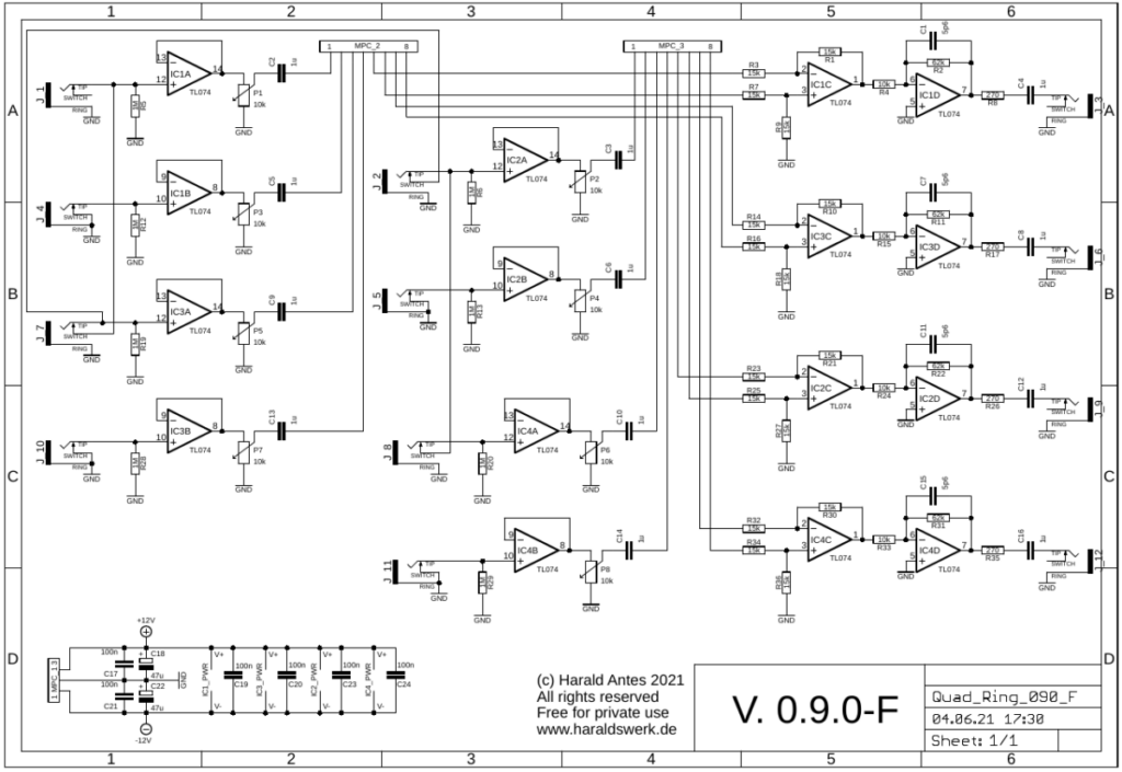
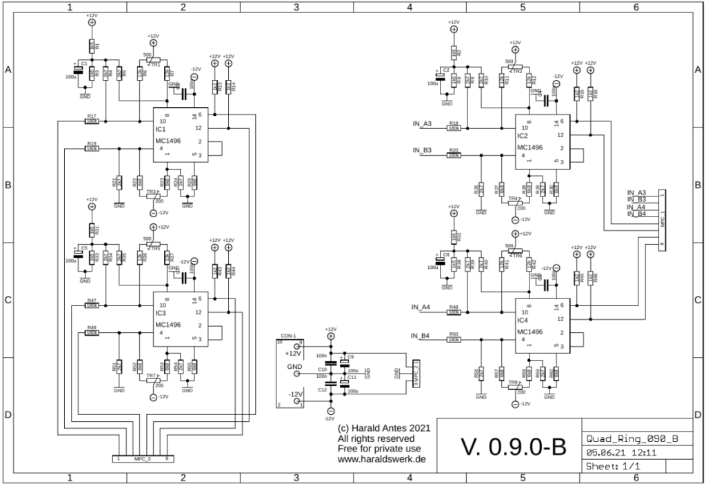
This is the 12V Euro version of my NGF dual version. It uses the now obsolete LM1496 balanced modulator -demodulator. But you can still source them and I have some in my stock. So I decided to make a PCB and module. I started with the original Elektor Formant schematic published in “Formant Erweiterungen” p35ff. I left out the microphone and envelope follower part because I already have such modules. I have added input buffers and raised the signal level to my 10Vpp used throughout my system.
Specs and features
Quad Ringmodulator
10Vpp input and output
Runs on +/-12V and +/-15V
Power consumption around 70mA each rail
The documentation and the Gerber files for download can be found in my website.
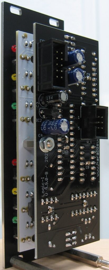
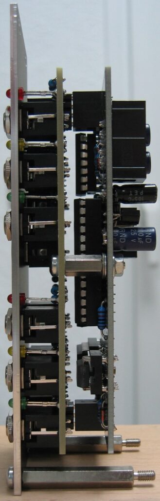
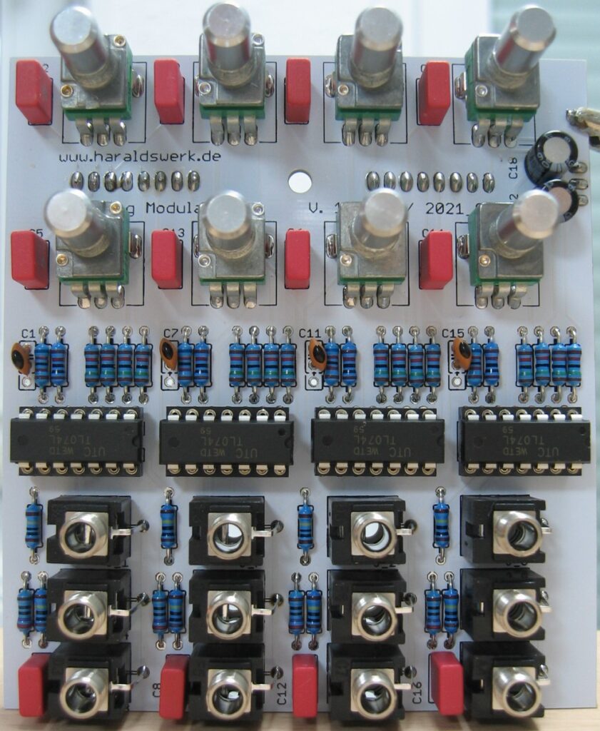
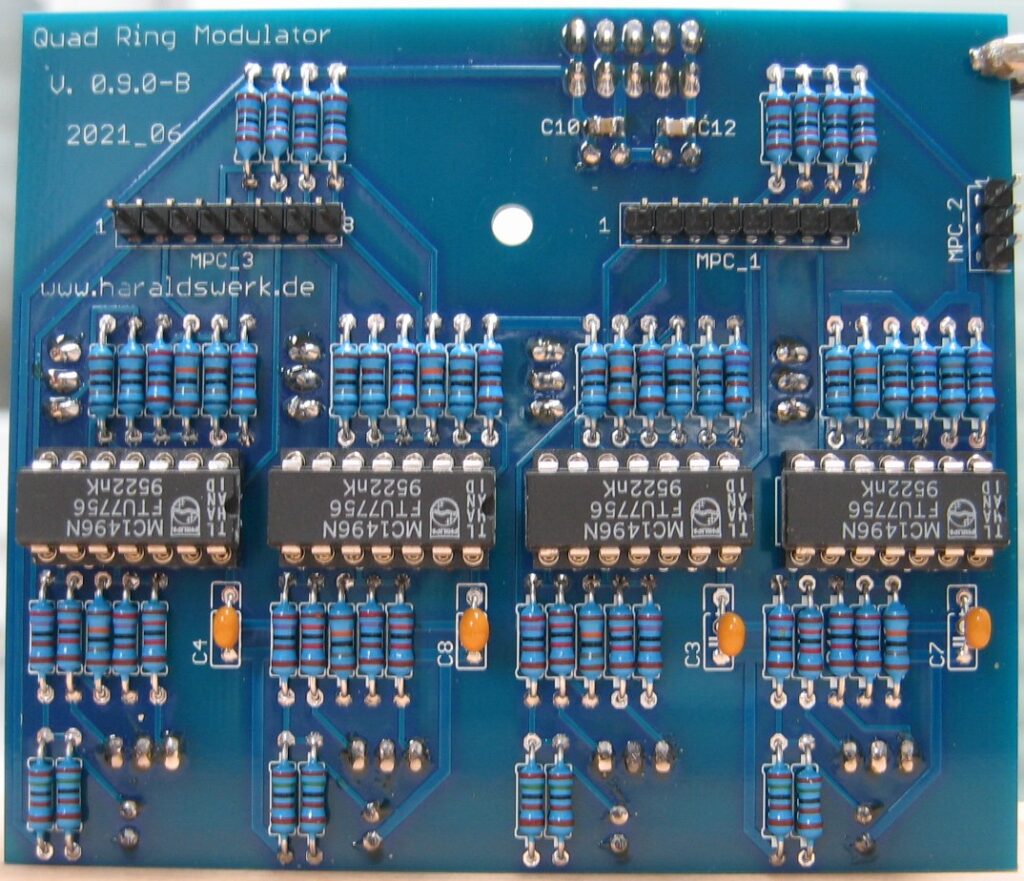
Quad Ringmodulator: Schematic control boardQuad Ringmodulator: Schematic main boardQuad Ringmodulator: Populated control PCBQuad Ringmodulator: Populated main PCBQuad Ringmodulator: Back viewQuad Ringmodulator: Side view
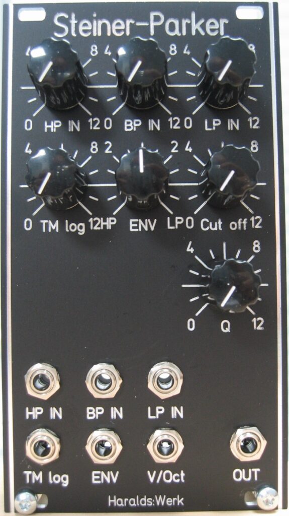
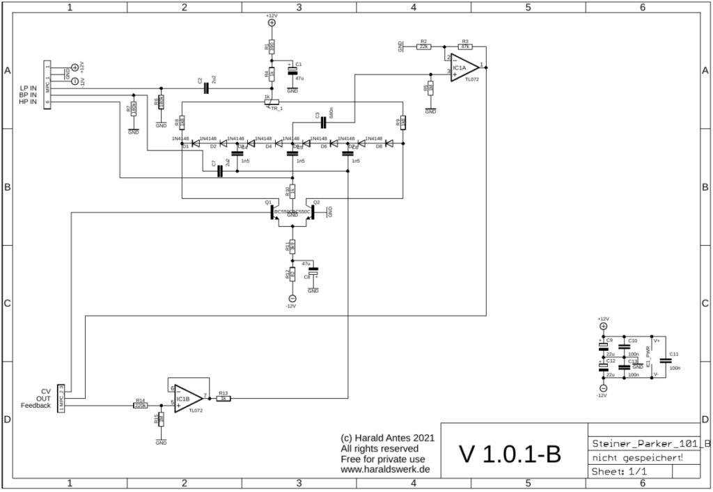
This is my take on the Steiner Parker filter. It is based an article in Electronic Design 25, December 6. 1974. You can find various implementations on the net. Very interesting are those from YuSynth and Ken Stone. You can still find them on the web as well as the original article. With my input stage it is possible to use the three filter inputs LP, HP, BP in parallel. The LP input is normalized to the others, so only one patch cable is needed. All inputs have attenuator.
Specs and features
Low pass, high pass, band pass input with attenuator
Positive and negative ENV control with sign changer
CV inputs for linear TM, log TM, envelope, V/Oct tracking and emphasis
Runs on +/-12V and +/-15V (with minor resistor value changes for best performance)
Power consumption below 20mA each rail
The documentation and the Gerber files for download can be found in my website.
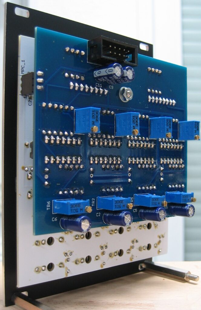
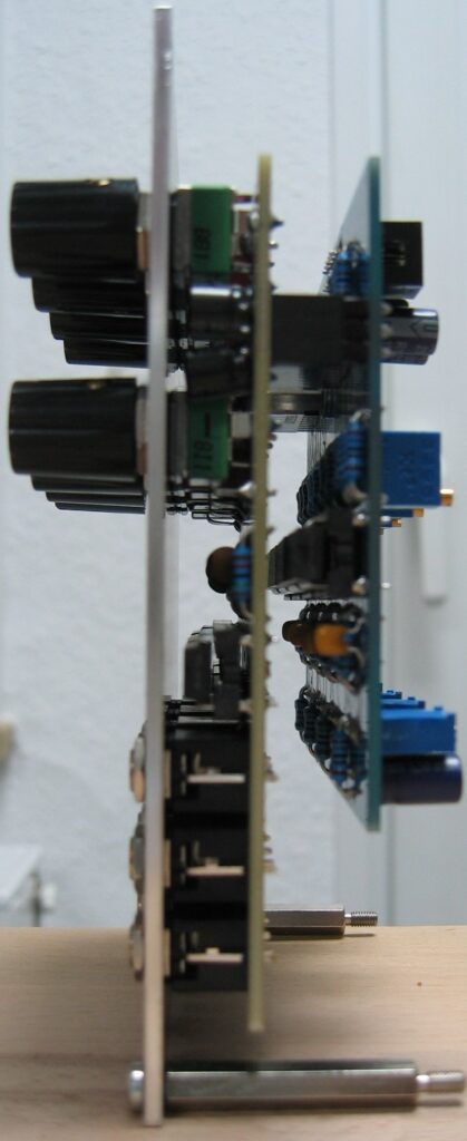
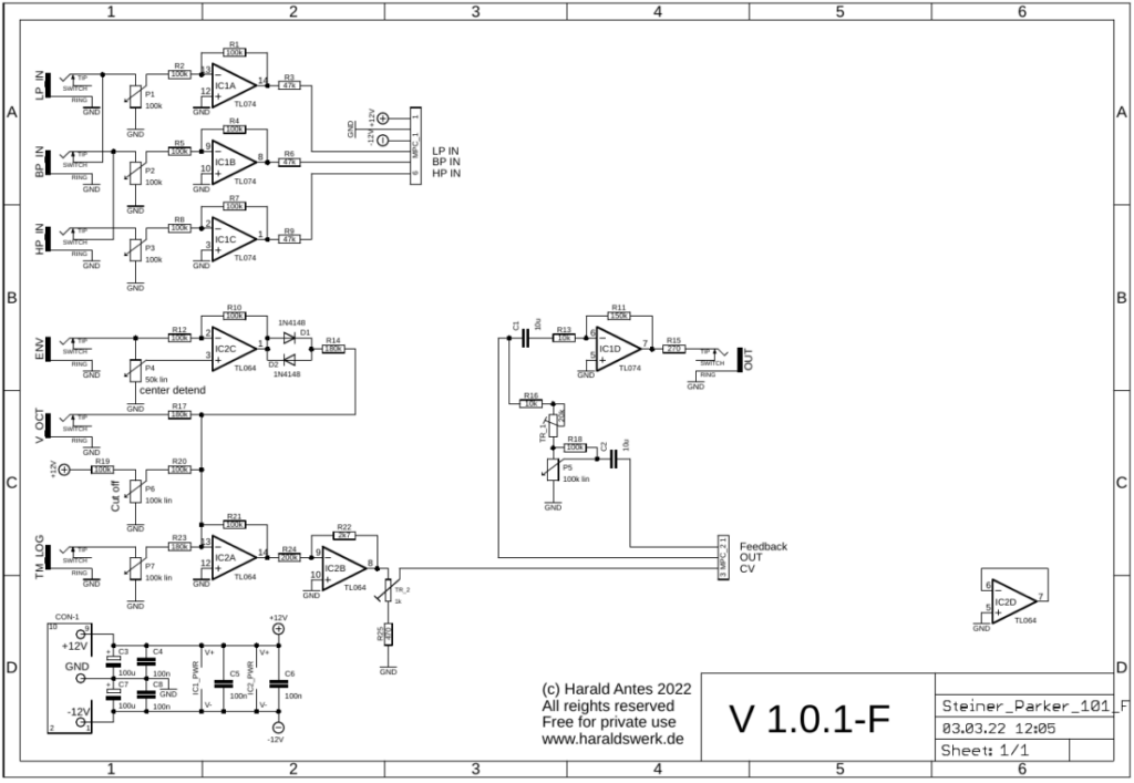
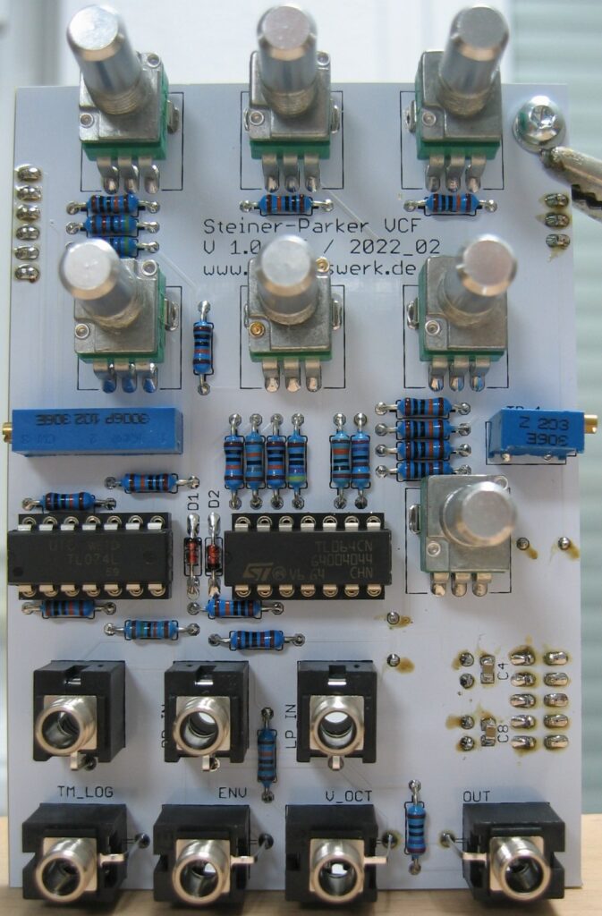
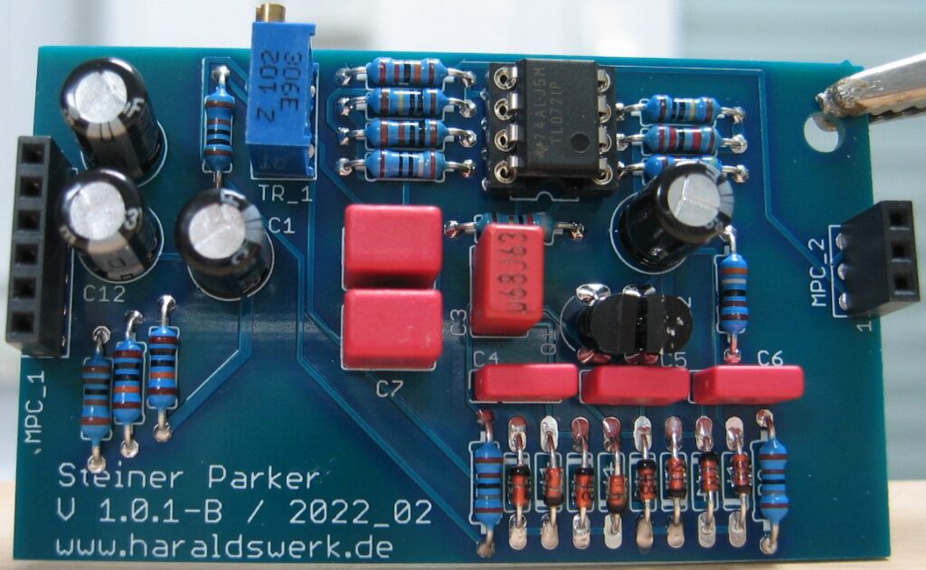
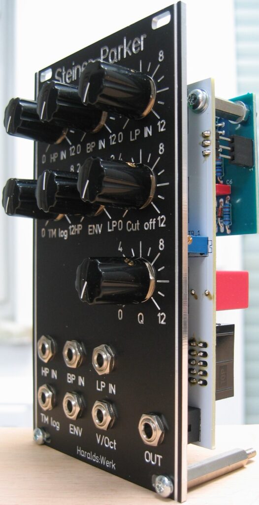
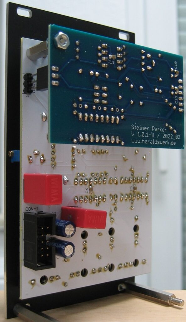
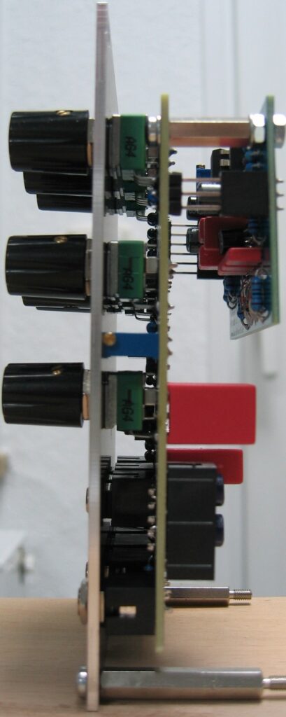
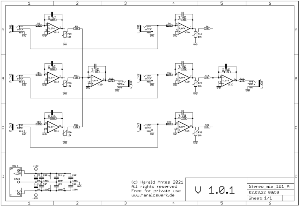
Steiner Parker VCF: Schematic control boardSteiner Parker VCF: Schematic main boardSteiner Parker VCF: Populated control PCBSteiner Parker VCF: Populated main PCBSteiner Parker VCF: Half front viewSteiner Parker VCF: Back viewSteiner Parker VCF: Side view
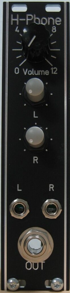
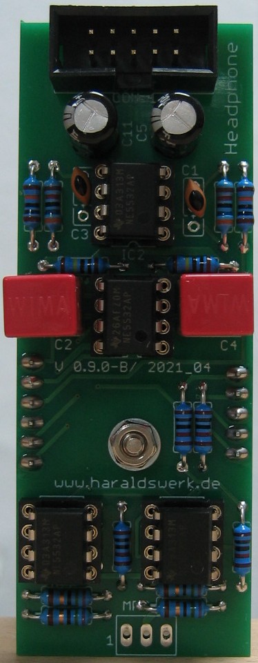
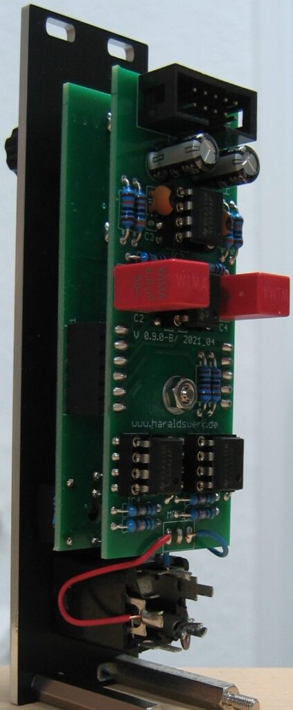
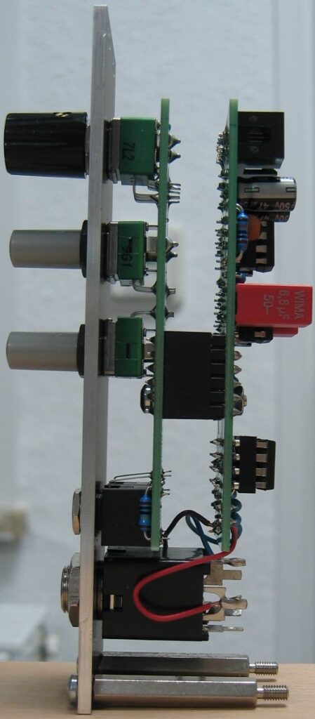
Not that much to say here. Simply a Headphone Amplifier. Based on Douglas Self “Small Signal Audio Design” second edition pg.560 and pg.33 fig.1.12
Simple dual amplifier with opamp-array (multipath amplifier).
Specs and features
Drives headphones in the range from 50R to 600R
Runs on +/-15V and +/-12V
Power consumption around 25mA each rail
The documentation and the Gerber files for download can be found in my website.
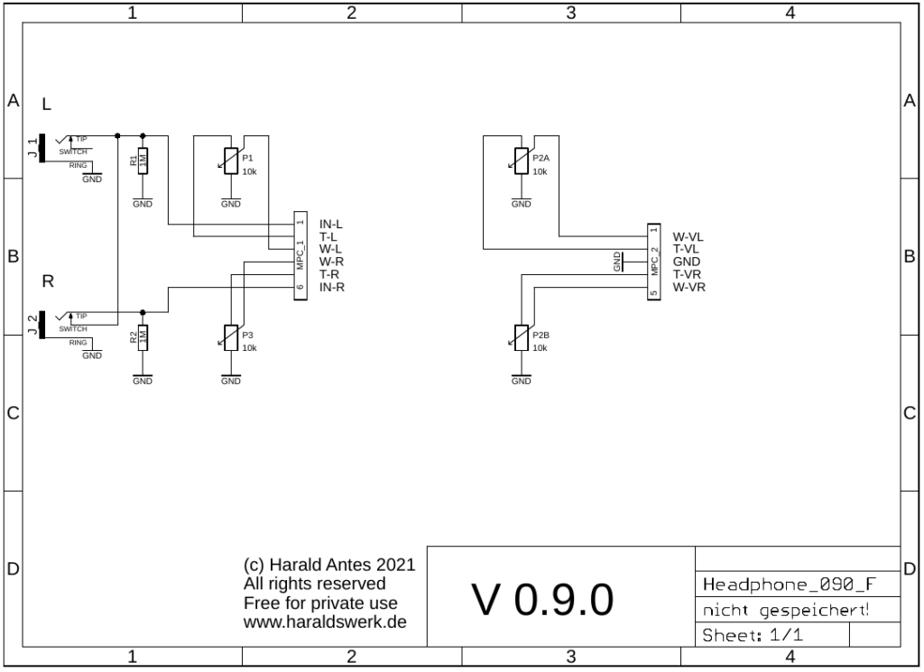
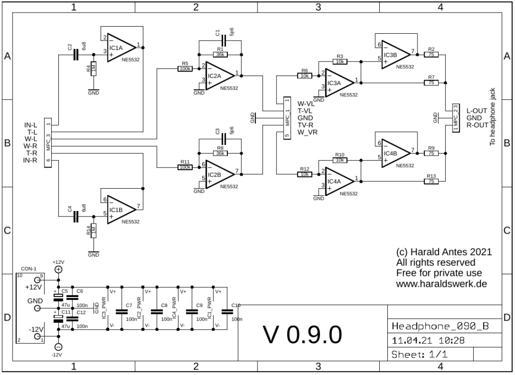
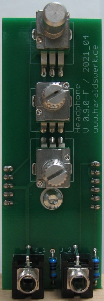
Headphone Amplifier: Schematic control boardHeadphone Amplifier: Schematic main boardHeadphone Amplifier: Populated control PCBHeadphone Amplifier: Populated main PCBHeadphone Amplifier: Back viewHeadphone Amplifier: Side view
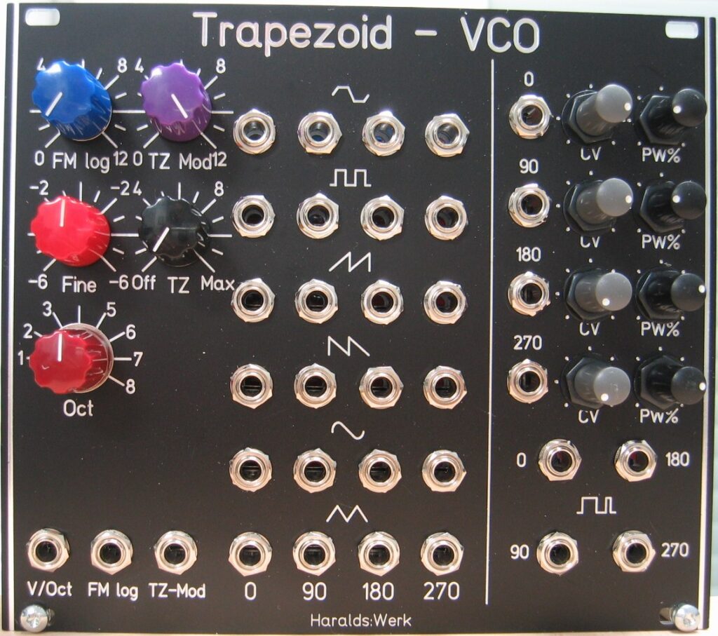
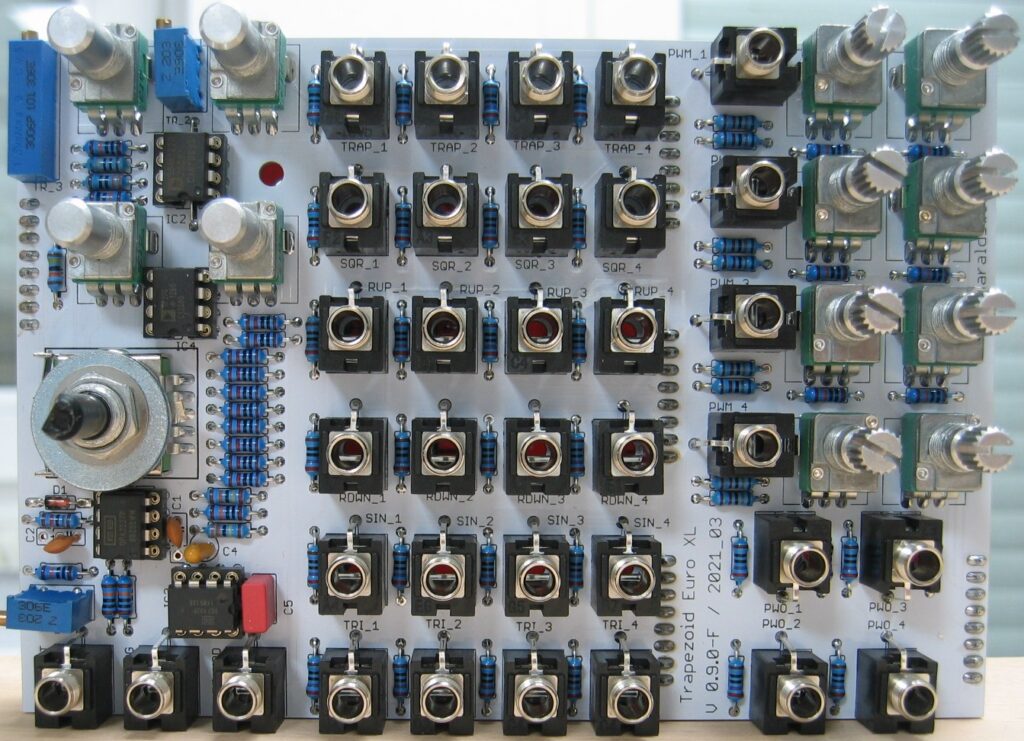
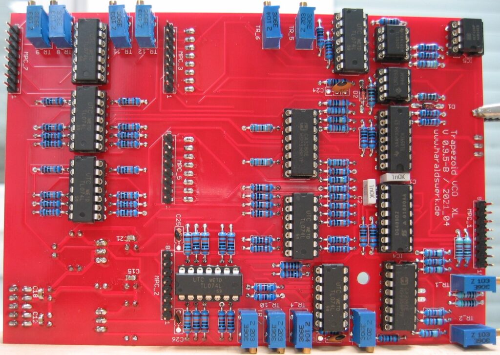
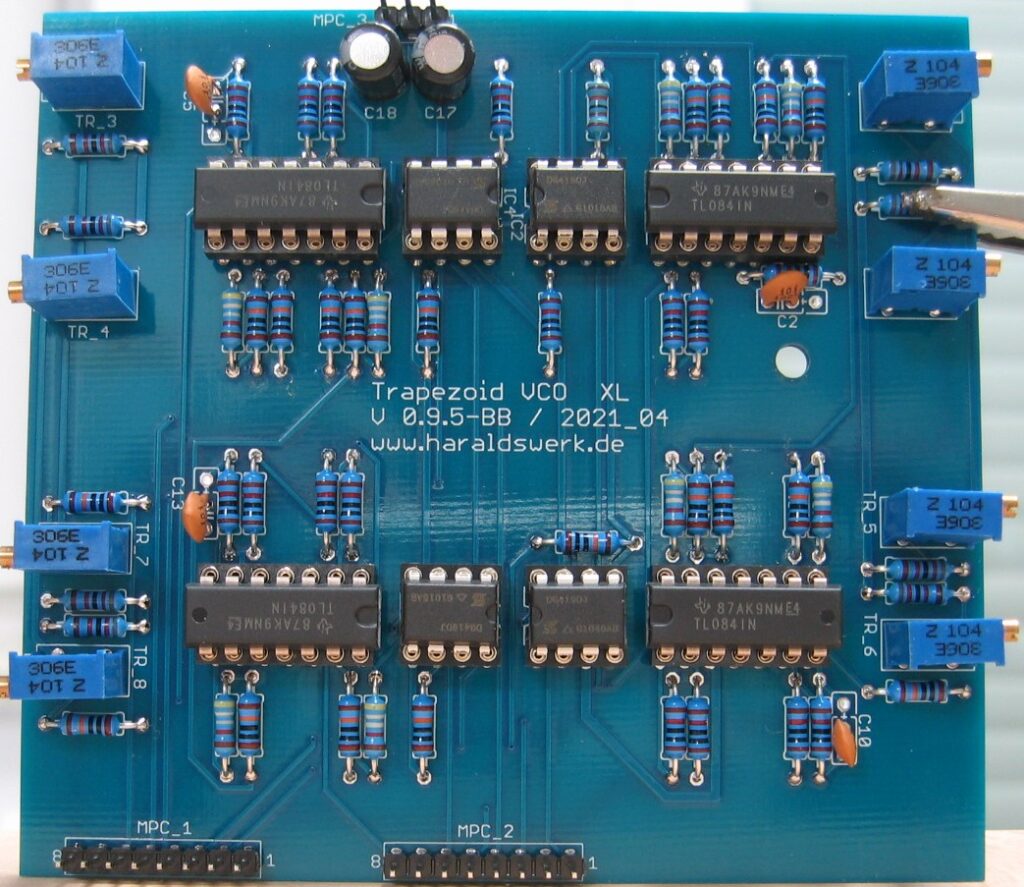
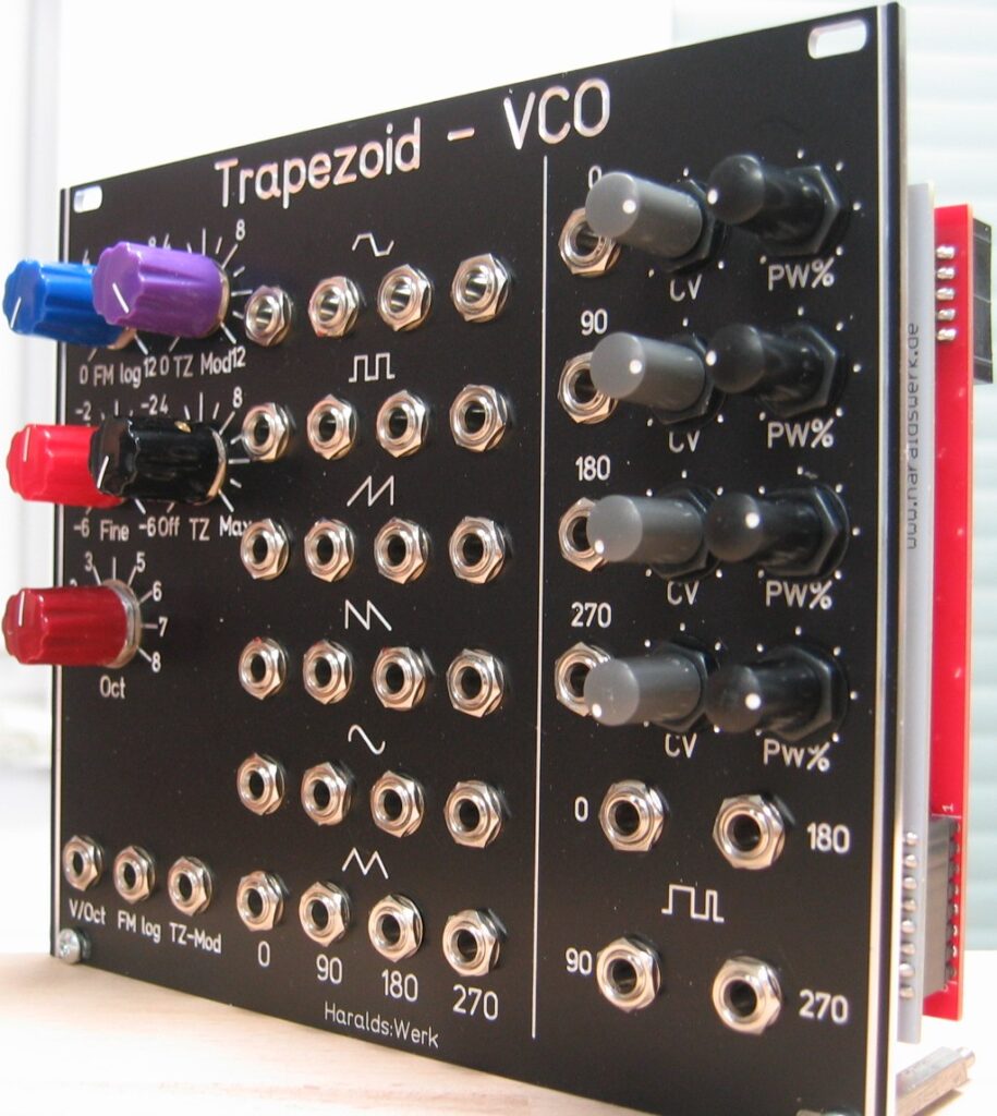
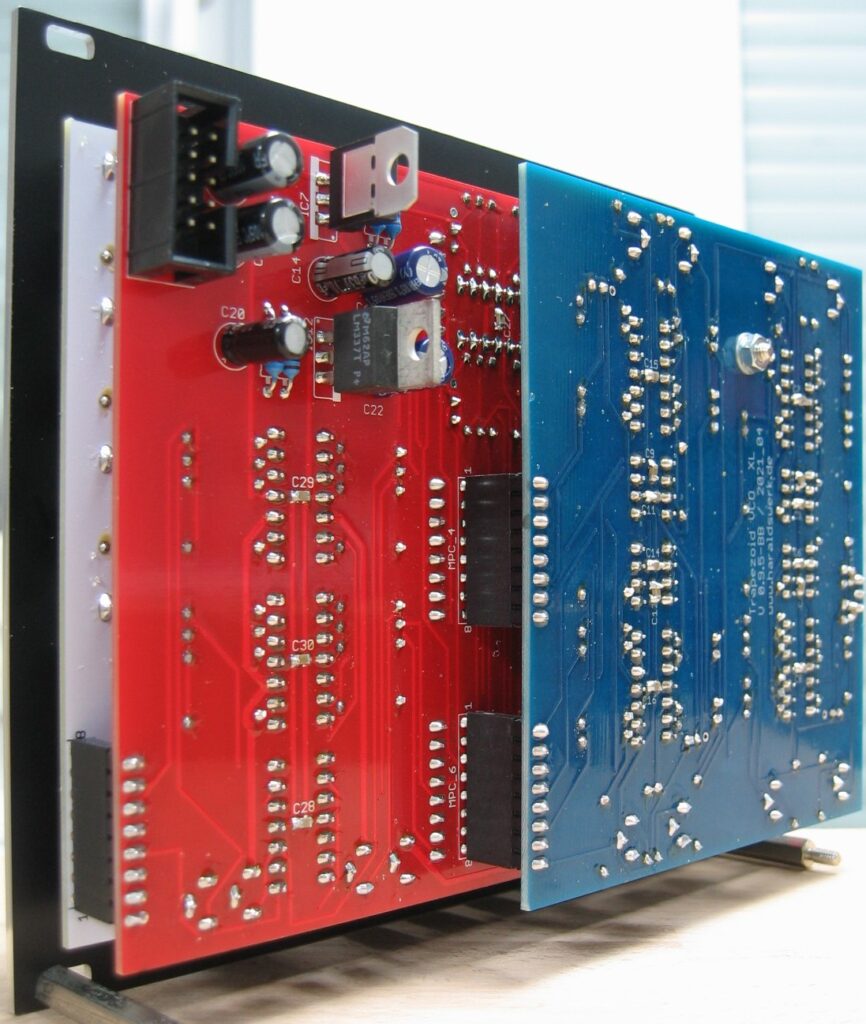
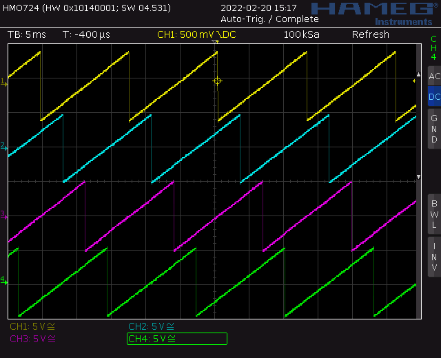
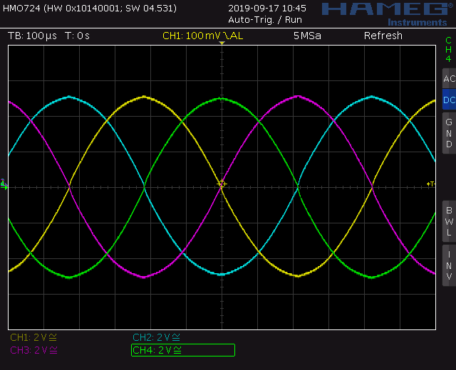
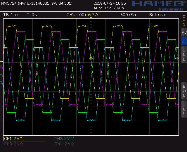
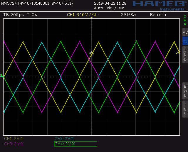
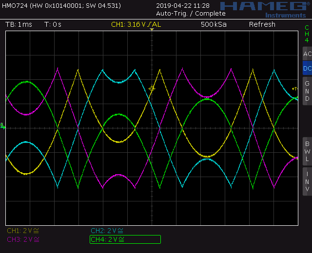
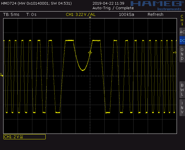
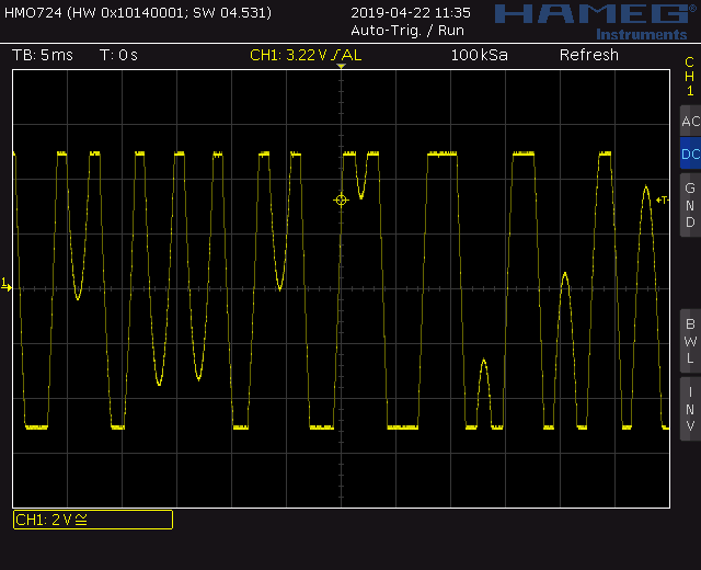
This is my extended version of the Trapezoid VCO core designed by Don Tillman. My first implementation for a 15V banana system with separate waveshaper can be found here. My second implementation for a 15V banana system with integrated waveshaper can be found here.This time I moved on to the 12V Eurorack format. The core is still based on the original design from Don (used with permission). I found the original article and schematic about the Trapezoid VCO on Don Tillman’s site (Link to original article from 19 July 2003). The article consists off three parts with the core implementation in part 2. I kept the basic idea and changed nearly everything else. I use an other exponentiator scheme and temperature stabilization. Another reference voltage device is used. A octave switch is added. And quadrature square outputs are implemented. As well as the additional waveforms triangle, sine, ramp up, ramp down and pulse.
For the extended Version I added the two missing outputs for ramp up, ramp down and pulse. Now this VCO has all the usual wave outputs, all 90deg apart.
Specs and features
Trapezoid quadrature output
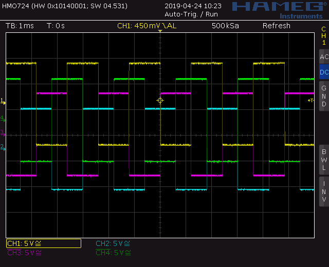
Square quadrature output
Triangle quadrature output
Sine quadrature output
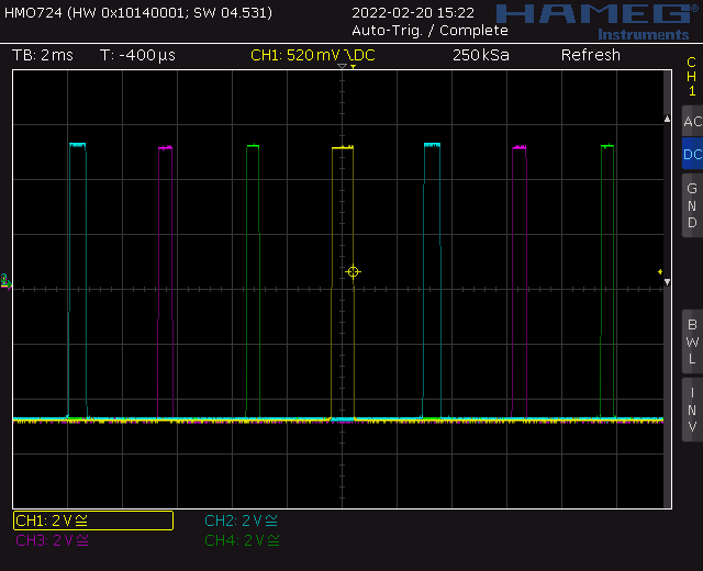
Pulse output, 0deg, 90deg, 180deg, 270deg
Ramp up output 0deg, 90deg, 180deg, 270deg
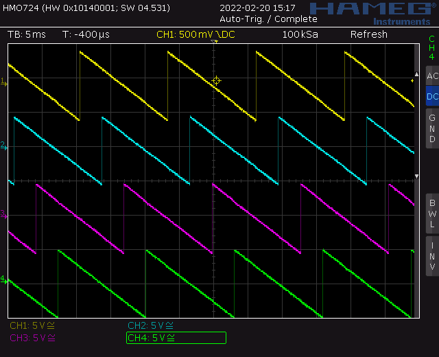
Ramp down output 0deg, 90deg, 180deg, 270deg
Octave switch
Through zero modulation
PWM input for 0deg, 90deg, 180deg, 270deg pulse
V/Oct, FM log and trough zero CV input
Temperature compensated
Fine frequency setting
Runs on +/-15V and +/-12V
Power consumption around 150mA each rail
The documentation and the Gerber files for download can be found in my website.
There are to much schematic to post here. Please refer to my website. Only pictures here.
Trapezoid VCO eXtended: Populated control PCBTrapezoid VCO eXtended: Populated main PCB 01Trapezoid VCO eXtended: Populated main PCB 02Trapezoid VCO eXtended: Halve front viewTrapezoid VCO eXtended: Back viewTrapezoid VCO: Screenshot pulse outputsTrapezoid VCO: Screenshot square outputsTrapezoid VCO: Screenshot ramp down outputsTrapezoid VCO: Screenshot ramp up outputsTrapezoid VCO: Screenshot sine outputsTrapezoid VCO: Screenshot trapezoid outputsTrapezoid VCO: Screenshot triangle outputsTrapezoid VCO: Through zero modulationTrapezoid VCO: Through zero modulationTrapezoid VCO: Through zero modulation
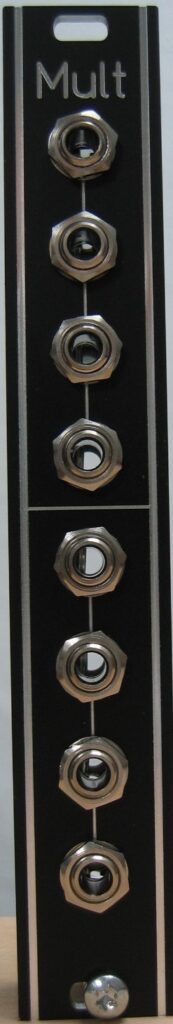
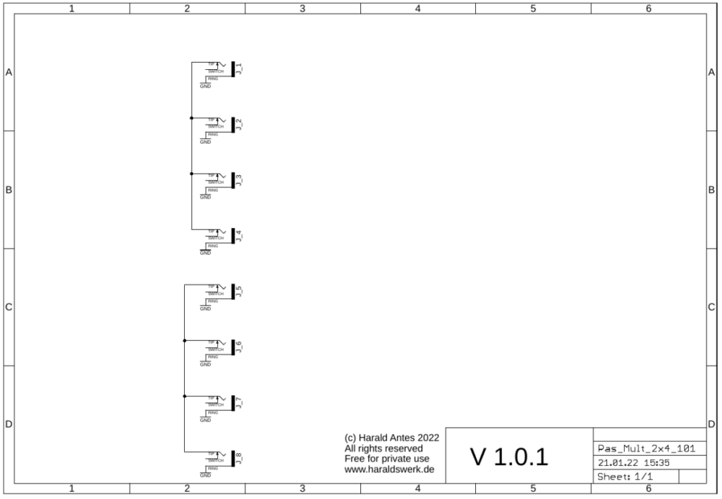
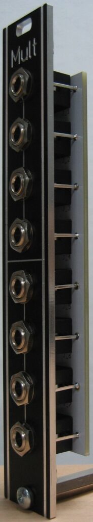
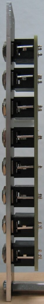
I already had a passive multiple with seven parallel in/outs. While using my synth I realized that I often use only a few of them. So I build this 2×4 multiple.
The documentation and the Gerber files for download can be found in my website.
Passive Multiple 2×4: SchematicPassive Multiple 2×4: Side viewPassive Multiple 2×4: Side view