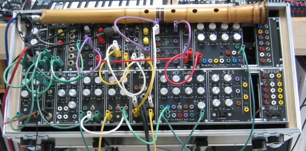
I have made some updates to my Shakuhachi to Synth project page. It presents the current patch and some more modules. The project is still ongoing.
I have made some updates to my Shakuhachi to Synth project page. It presents the current patch and some more modules. The project is still ongoing.
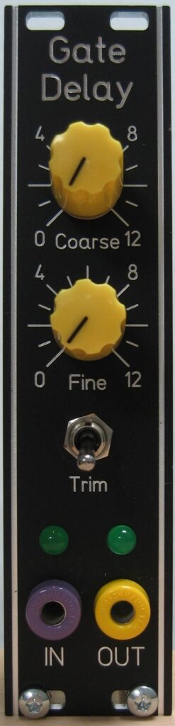
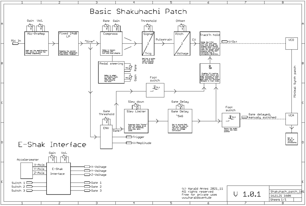
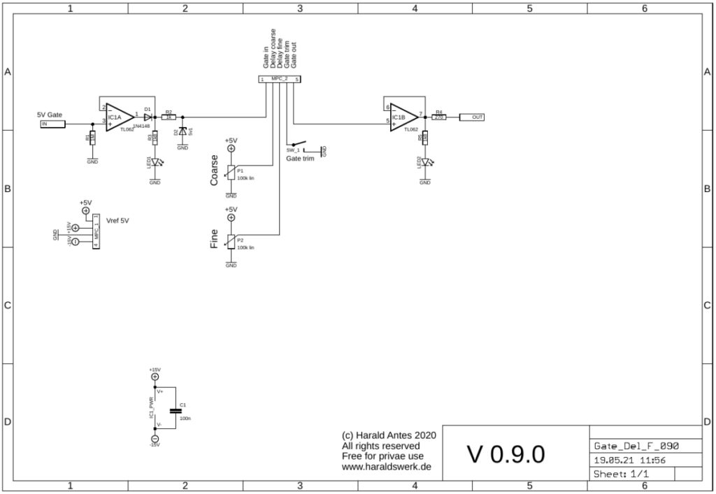
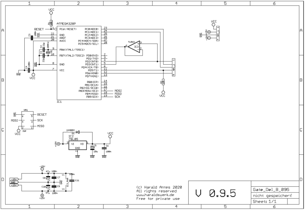
This module starts as a need for my Shakuhachi 2 Synth project. I was in need for a short Gate Delay of about 10ms (which is easy to realize). But then I thought about a more flexible solution with adjustable delay time and optional trimming the gate at the end. To be used elsewhere in the synth as well. So I came up with this solution. The hardware is still simple and the functionality lies in the software. So far I have only realized the function which I need for my Shakuhachi to Synth project. But you can easily improve about this with changing the software.
The documentation and the Gerber files for download can be found in my website.
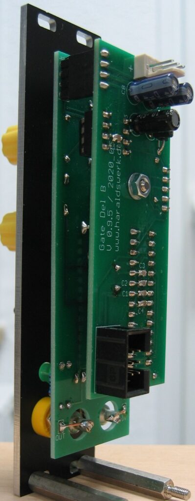
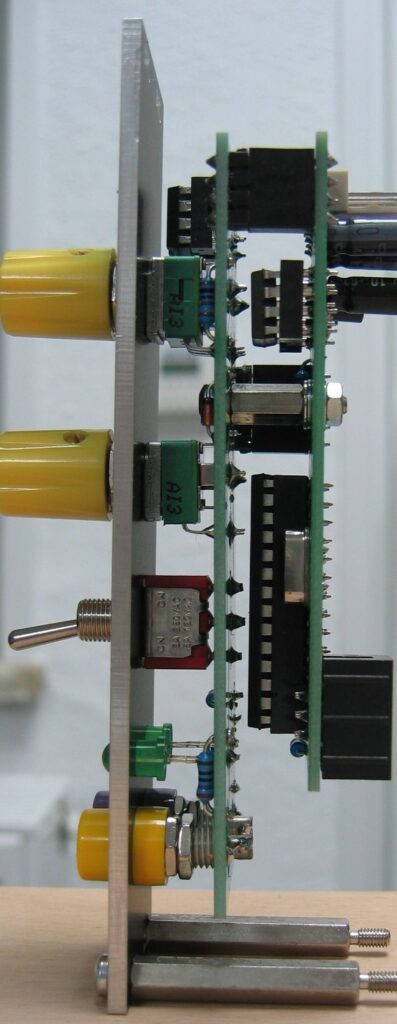
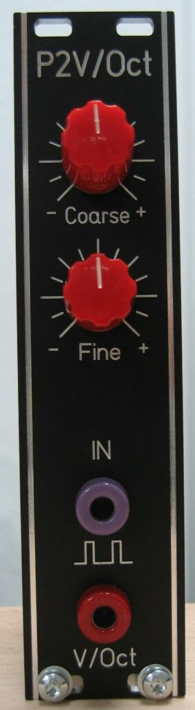
This is the software driven replacement for my all hardware pitch to voltage converter from my Shakuhachi to Synth project. The software driven approach has the advantage of easily adaption for different frequency ranges. In my case it is the range of the Shakuhachi. To change the range just adapt the software. It is completely temperature independent. The needed input is a pulse train derived from your original signal. You can use my Signal to Trigger converter to provide the pulse train. An offset voltage is added to the V/Oct output to fit the needs of your VCO (Synthesizer).
The documentation and the Gerber files for download can be found in my website.
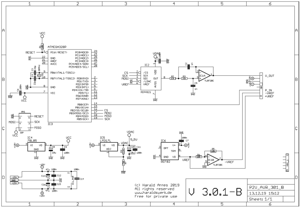
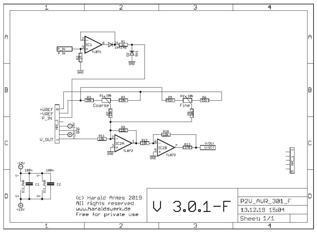
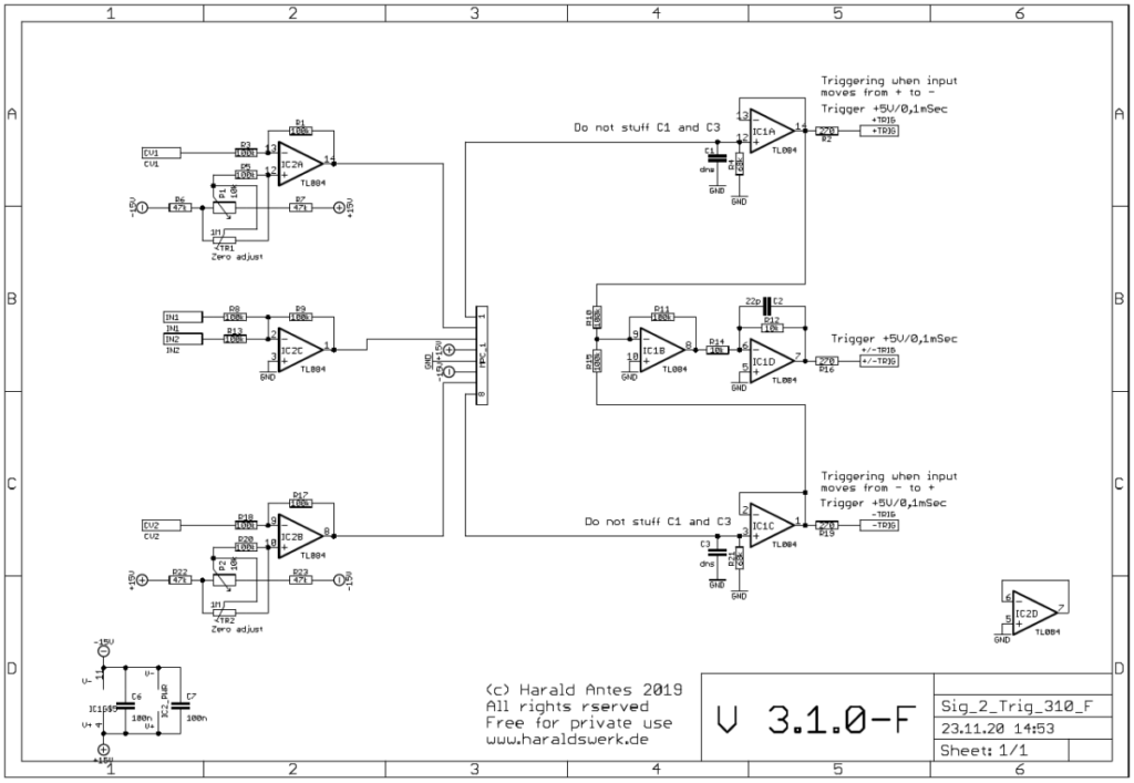
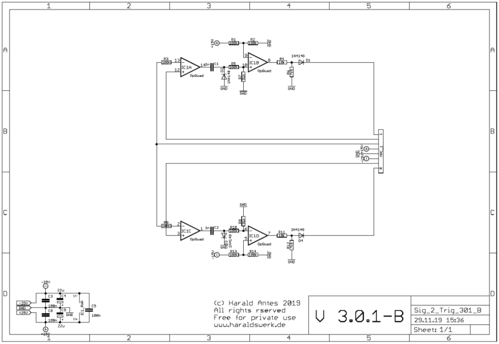
The incoming pulse train is feed to the microprocessor. IC1 (301-F) prevents the microprocessor from negative inputs. Zener D2 prevents from overvoltage. The trigger starts an internal timer of the microprocessor in input capture interrupt mode. The ticks are counted and the count is then looked up in a table. The lookup table provides the values for the V/Oct conversion. The read value is the send to the DAC MCP4921 which is follwed by a low pass (IC1A, 301-B)). IC2A (301-F) adds the offset voltage and IC2B (301-F) corrects the phase.
This is the revised version of my Limiter/Compressor. First built for my Shakuhachi to Synth project to handle the great dynamic range of the Shakuhachi. Here I left out the limiter and added a make up amplifier. The structure used is derived from “Small Signal Audio Design”, second edition by Douglas Self p682ff. The audio signal did not flow through a VCA as in many other implementations. Instead the compression is done by subtracting the audio signal at the output summing node according to the control voltage derived from the audio signal. The compression rate and the make up gain is adjusted by hand or/and optionally with foot pedals. The foot pedals are an additional option particularly made for wind players. It works without this option in your setup as well.
The documentation and the Gerber files for download can be found in my website.
When the ratio is set to zero and the gain to one the input signal passes through the circuitry unaffected (IC2C, IC2A IC6OTA1, IC6OTA2, IC2D). When the compression rate is turned up a DC voltage is derived from the input signal wit a precision full wave rectifier and some filtering (IC1A, IC1B, IC1C, IC1D). This voltage is used to open the VCA in the side chain (IC3OTA1, IC3OTA2, IC2B). The signal from the side chain is then subtracted from the main signal (R13, IC2A). The now compressed signal is then potentially amplified (IC6OTA1, IC6OTA2)
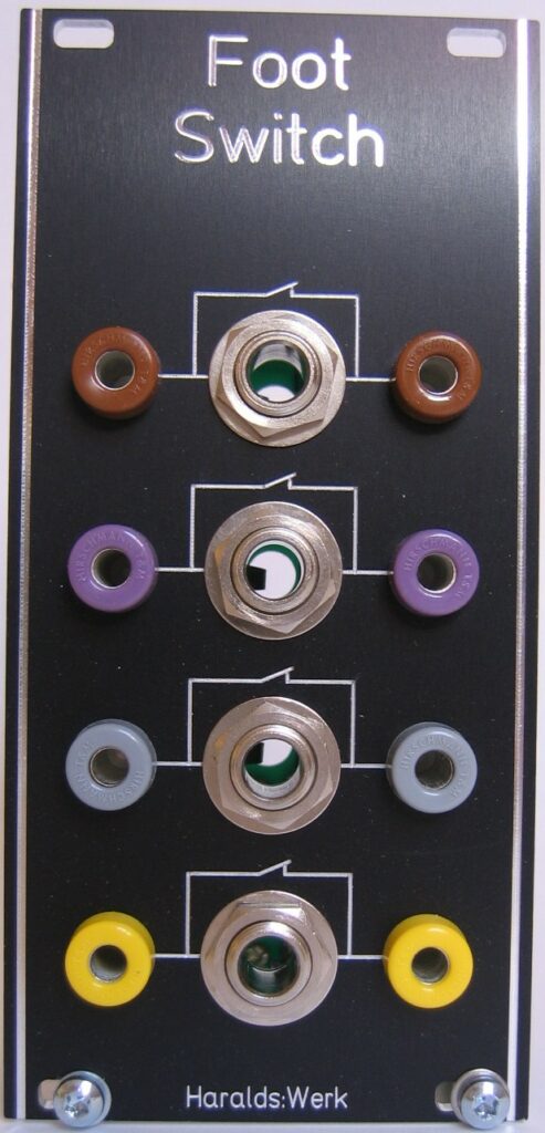
As a Shakuhachi player I need my hands on the flute. So I use me feet to manipulate parameters and switches on the synthesizer. This module was originally build for my Shakuhachi to Synth project to provide the possibility to connect foot switches with the synthesizer and keep the patch intact when they are removed. The signal is not routed through the foot switch. Instead CMOS switches are used, turned on and off with the foot switch. So the signal stays within the synthesizer and the connection to the foot switch carries only DC. Removing the foot switch does not interrupt the signal flow in the synthesizer.
The documentation and the Gerber files for download can be found in my website.
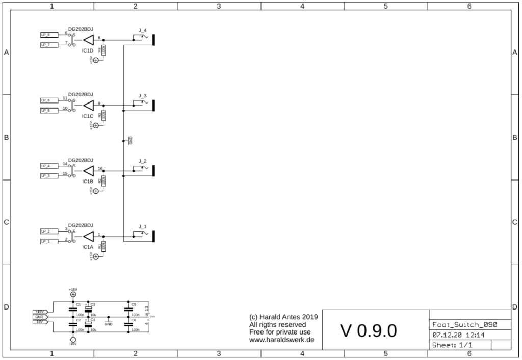
The switch in the DG202 is hold in on position with a 100k resistor against the positive rail. With a foot switch attached you can pull down the hold voltage when you close the foot switch.
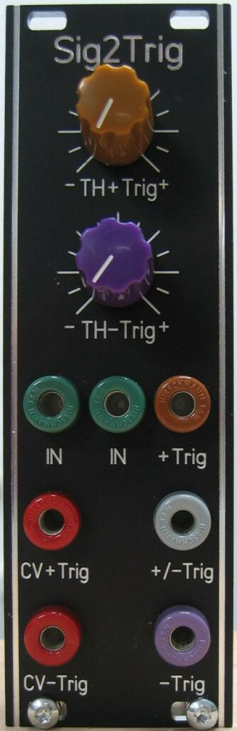
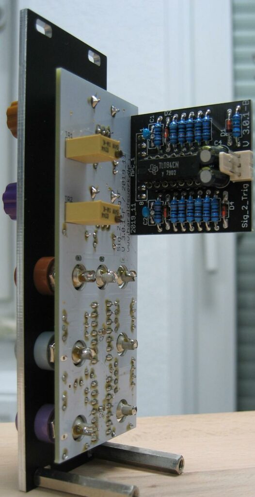
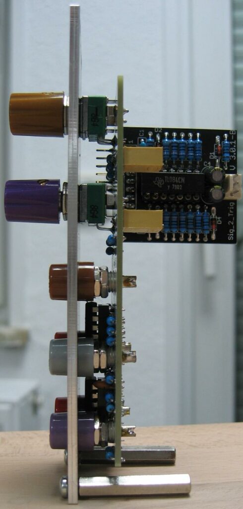
This module was originally build for my Shakuhachi to Synth project to provide the start/stop pulse for the Pitch to voltage converter. But it turned out to be much more useful. When you have the basics for your synthesizer like VCO, VCF, VCA, ADSR, LFO,… and some controllers and you want more, then using your keyboard to steer the synthesizer it is time for some modules to produce trigger signals out of different sources. Here is one of them. A signal to trigger converter. You can feed in a changing signal and every time the signal went through zero a trigger is generated dependent on the direction from where the zero point is crossed. You can add a threshold manually or CV controlled to move the zero point up or down as well. You can feed the signal in through input one ore two. When both inputs are used the signals are added together. When the signal crosses zero from positive to negative a trigger of about 0.1msec is generated at output -Trig. When the signal crosses zero from negative to positive a trigger of about 0.1msec is generated at output +Trig. Output +/-Trig provides both triggers. This output can be used to generate interesting rhythmic patterns when the threshold is set by a slowly moving CV or some DC offset is applied to the signal.
The documentation and the Gerber files for download can be found in my website.
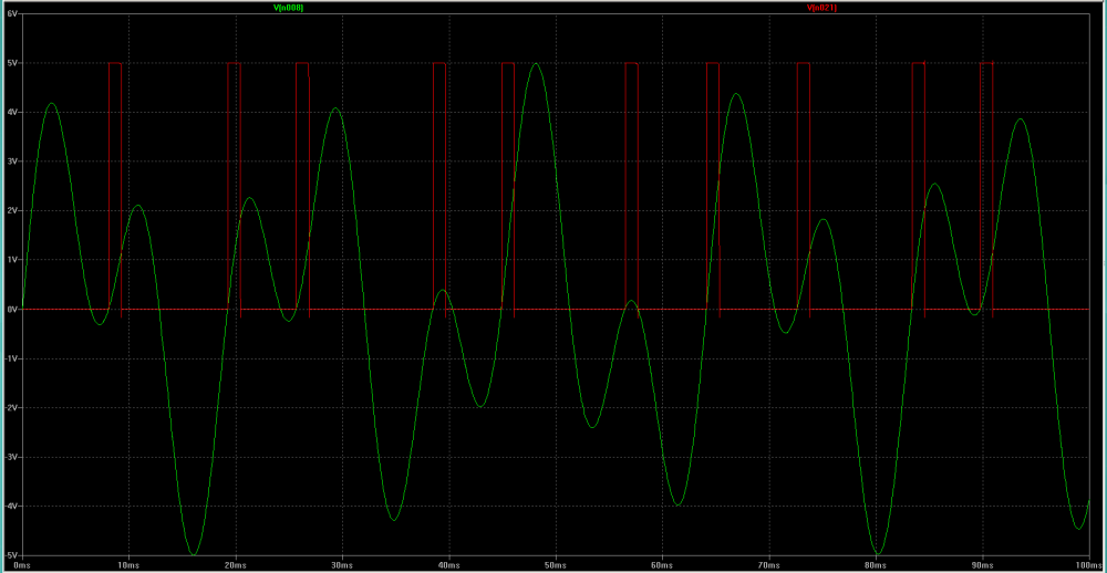
The incoming signals are summed up. Every time when the summed signal changes polarity (moving through zero) a trigger is generated. Moving from plus to minus generates a trigger at the negative trigger output, moving from minus to plus generates a trigger at the positive trigger output. Trigger length is about 0.1msec.
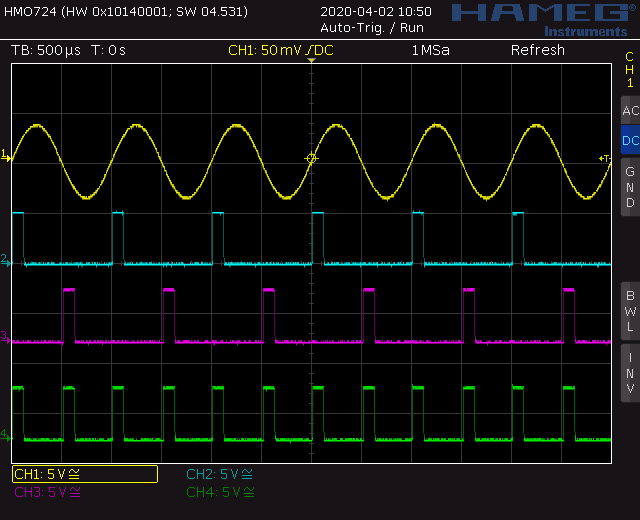
The uppermost line (Yellow) shows the input signal. The second line (Blue) shows the trigger when the input signal moves to the positive site. The third line (Purple) shows the trigger when the input signal moves to the negative site. On the fourth line (Green) you can see both triggers added. This picture is taken without any threshold.
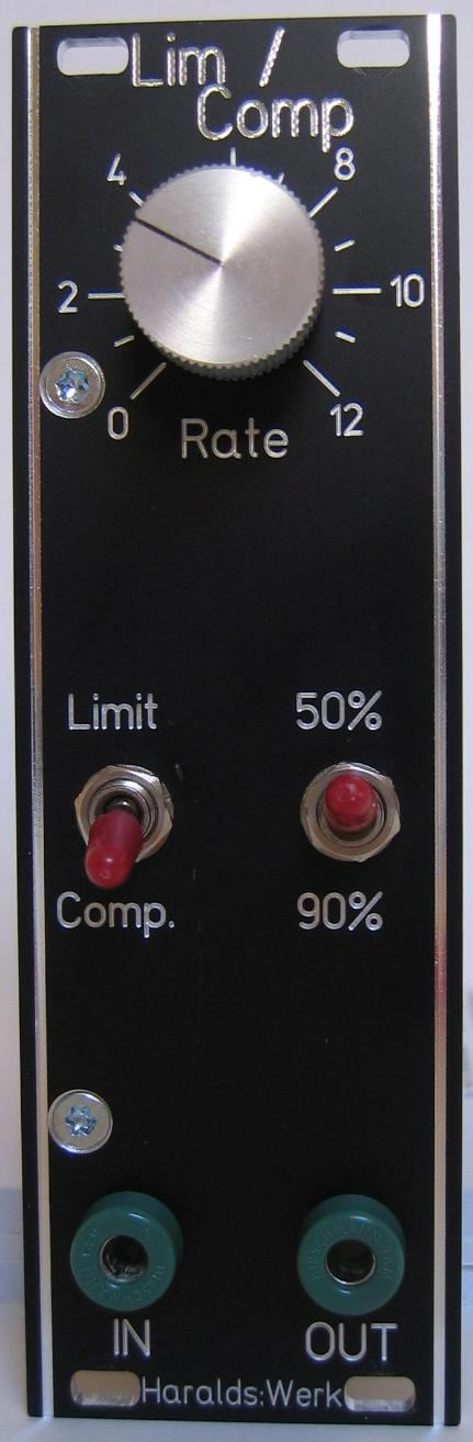
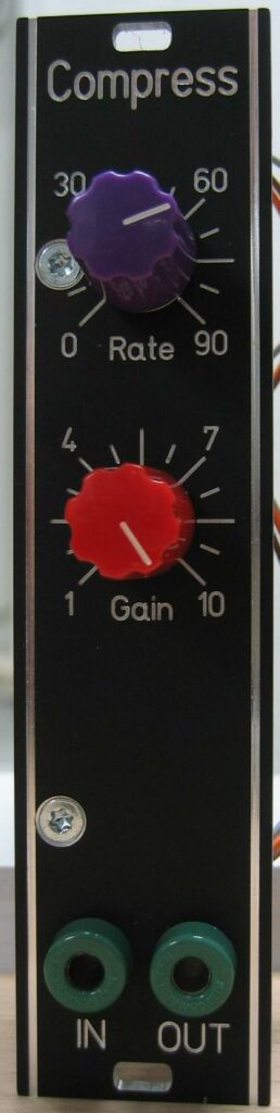
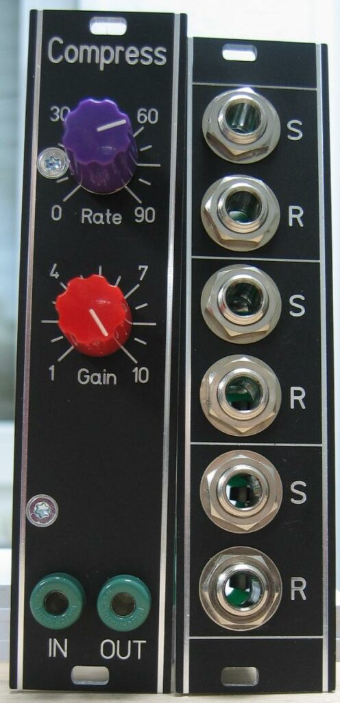
Limiter / Compressor front view
To handle the great dynamic range of the Shakuhachi I needed a compressor for my Shakuhachi 2 Synth project. Because a limiter is not that different I added this feature as well. This comes in handy with my Vocoder project also. The structure used here is derived from “Small Signal Audio Design” by Douglas Self p682ff. The audio signal did not flow through a VCA as in many other implementations. Instead the compression or limitation is done by subtracting the audio signal at the output summing node according to the control voltage derived from the audio signal.
Specs and features
• Switch compress or limit
• Switch Compression/Limit rate 50% or 90%
• Compression/Limit rate adjustable 0–max
• Runs on +/-15V and +/-12V (with minor resistor changes)
• Power consumption below 15mA each rail
The documentation for download can be found in my website.
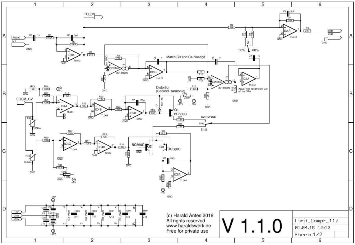
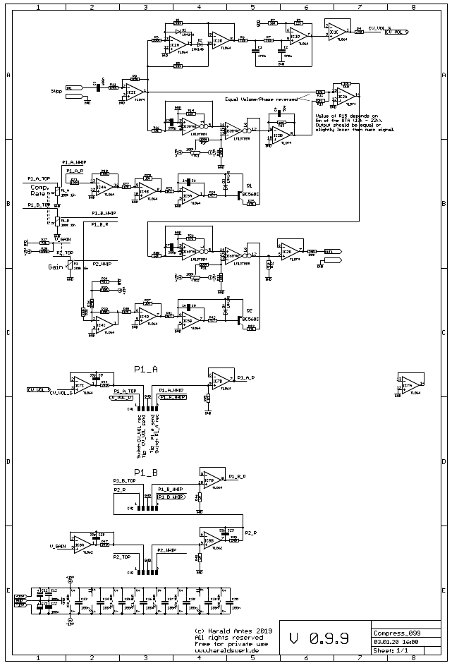
Limiter / Compressor schematic 01
The audio signal flows unaffected through IC1A/B. When the compressor – limiter kicks in the inverted signal is added (=subtracted) at the summing node of IC1A. The signal level to subtract is regulated through a Sims VCA. The CV generation for the VCA is pretty standard. Linear for the compressor and exponential for the limiter.
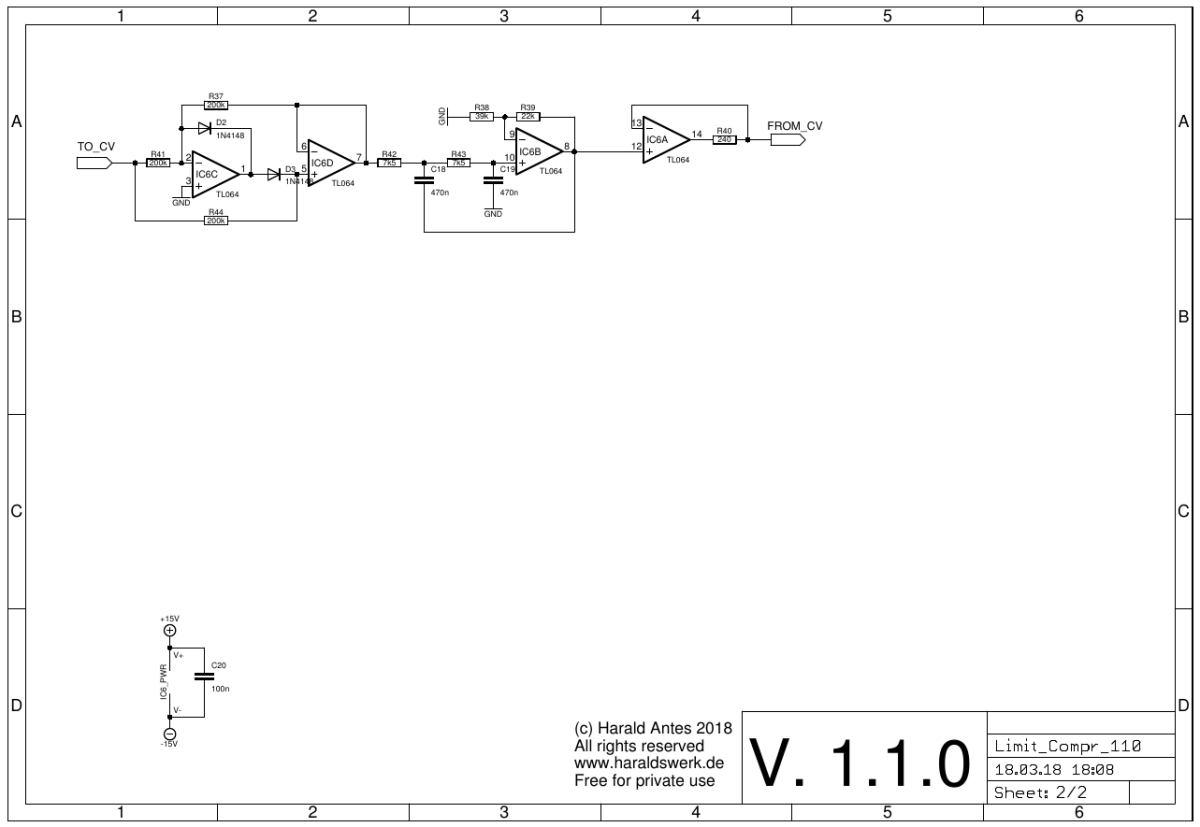
Limiter / Compressor schematic 02
Precision full wave rectifier with filter to generate the control voltage for the VCA from the audio signal.
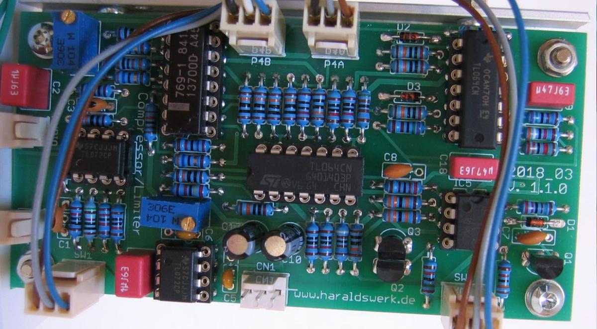
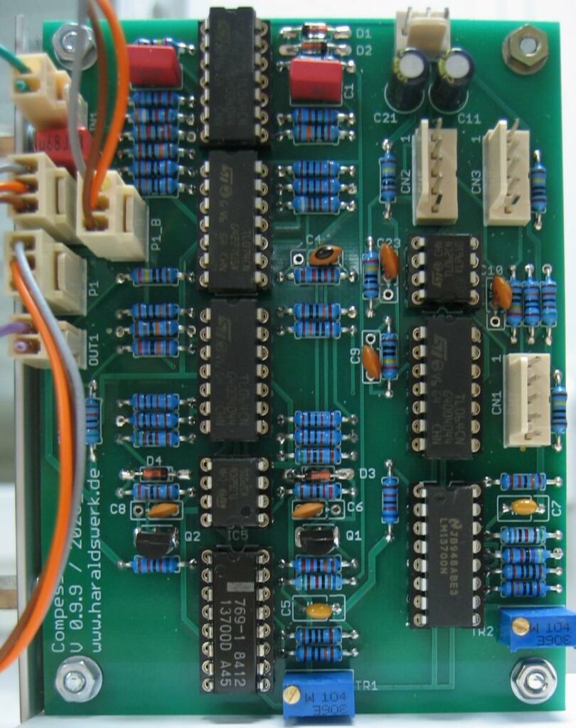
Limiter / Compressor populated PCB
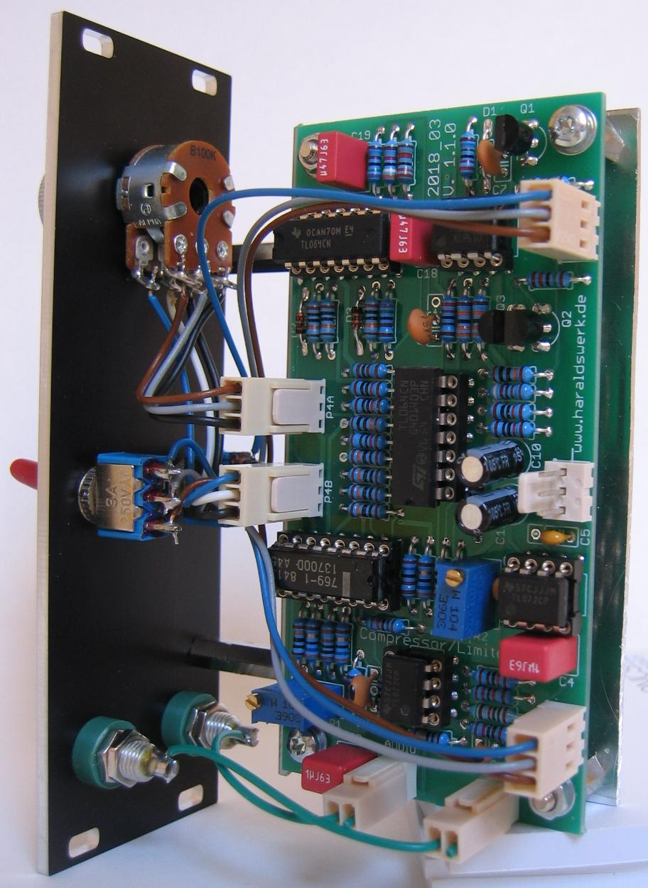
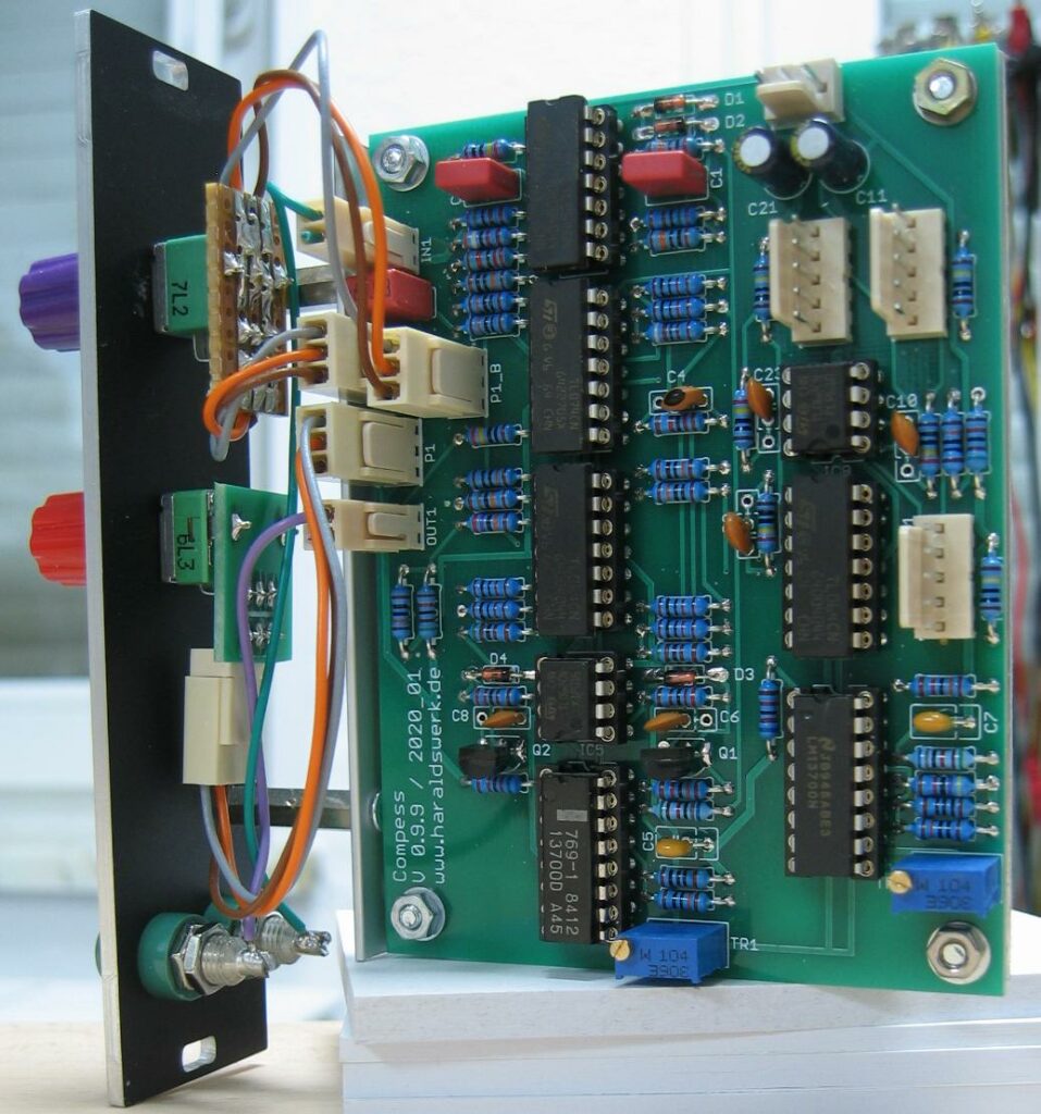
Limiter / Compressor back view
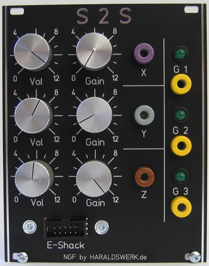
Shakuhachi 2 Synth Project: E-Shak Interface
Here is the interface for my “E-Shak”. The input comes from an exoskeleton attached to a Shakuhachi. It is connected to the interface with a 10 wire ribbon cable. The exoskeleton is used as addition to the pitch 2 voltage converter and the ENV follower. Inputs are three voltages from a three axis accelerometer (x, y, z) and three touch sensitive switches (Gate 1, 2, 3). The output range foe x, y, z is adjustable in gain and volume. This gives a wide variability in usage. The three gates are 5 V. The state is indicated with LED.
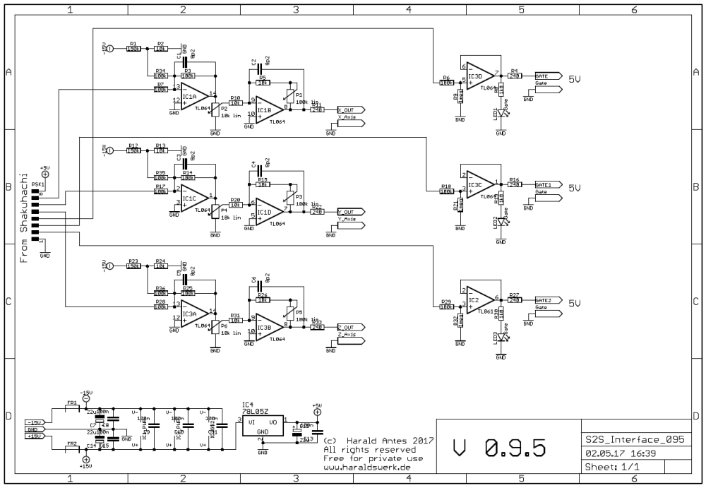
Shakuhachi 2 Synth Project: E-Shak Interface schematic
The voltage from the accelerometer is buffered and level shifted in the first operational amplifier. The amplification of the second stage is adjustable so you can spread the signal range. The inputs from the touch sensitive switches are buffered and signaled with LED.
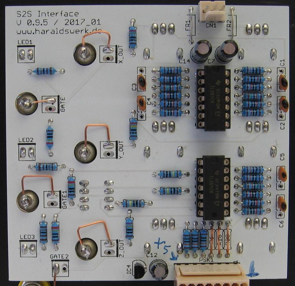
Shakuhachi 2 Synth Project: E-Shak Interface stuffed PCB
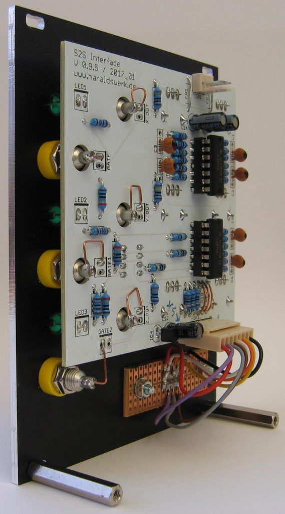
Shakuhachi 2 Synth Project: E-Shak Interface back view
Shakuhachi 2 Synth Project: E-Shak Interface side view
Here is the pitch 2 voltage converter for my Shakuhachi 2 Synth project. It is based on an article in Electronotes EN#84 p5-p9 from Robert Iodice. It consist of some control logic and a 12bit DA converter. I have found a fault in the control logic and simplified the DA converter. The original only had a V/Hz output, so I added a V/Oct output.
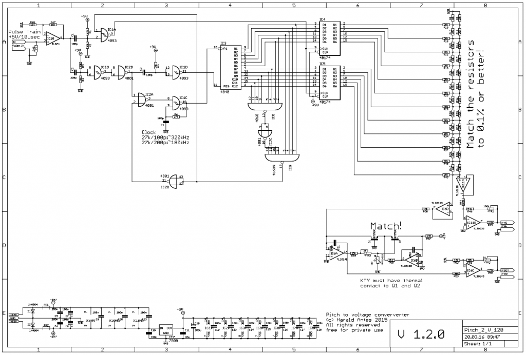
Pitch 2 voltage converter: schematic
The circuitry takes a pulsetrain and converts it to a voltage according to the frequency of the pulsetrain.
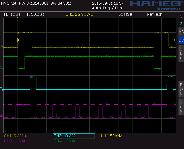
Pitch 2 voltage converter: timing diagram
A clock of about 320kHz is used to drive a 12bit binary counter. The outputs of which are fed through latches and then to a 12-bit DA converter. The voltage is then converted to V/Oct characteristic with a anti-log generator. The additional circuitry is to control the timing sequence, gating the clock signal and generating a flag signal. The flag is generated when the outputs of the counter all reach a high level. This condition is reached when the input is removed or the input frequency drops below the systems lower frequency limit.
The circuit has the advantage of sampling very quickly (only two pulses required) and holding indefinitely.
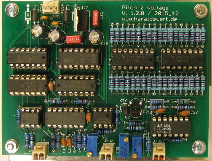
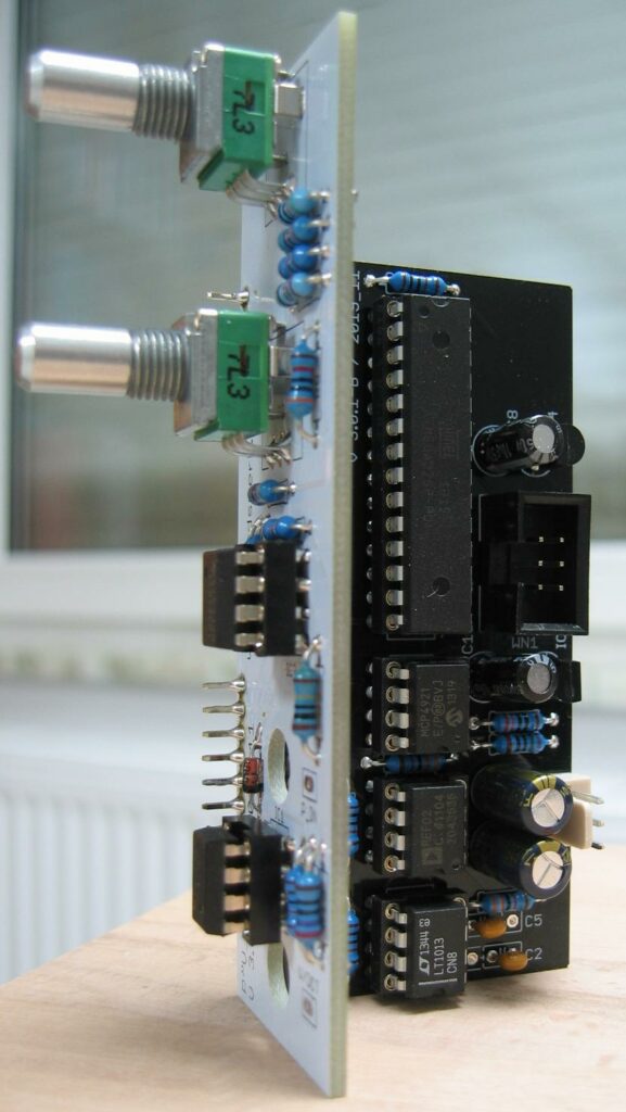
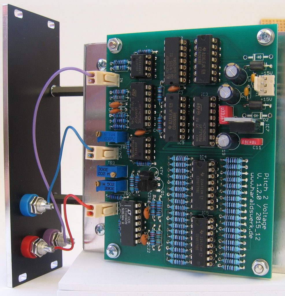
Pitch 2 voltage converter: stuffed PCB
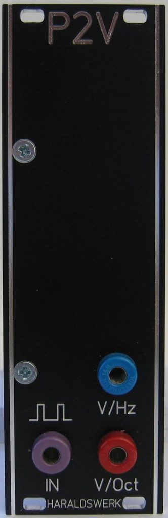
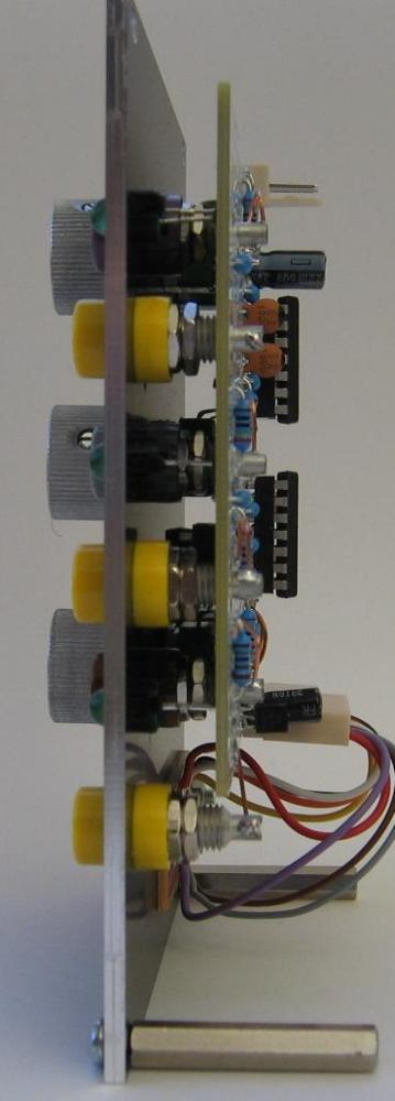
Pitch 2 voltage converter: Front
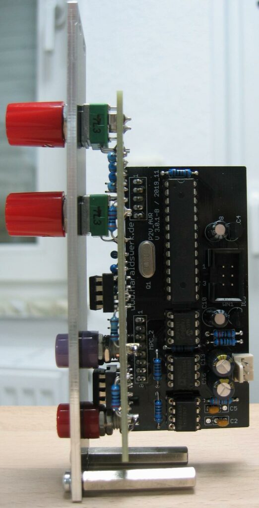
Pitch 2 voltage converter: Back
This is the first stage of the pitch to voltage converter for my Shakuhachi 2 Synth project. The incoming signal from the microphone is bandpass filtered and a pulse train is derived from the signal. This is possible because the signal/waveform of the Shakuhachi is nearly sinusoidal. At least in the higher register. As you can see on the screenshot.
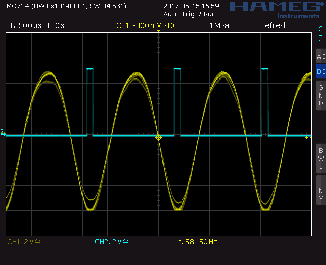
Shakuhachi 2 Synth Procect: Shakuhachi signal Ro kan
In the lower register you need to adjust you playing a bit. Not in pitch but in timbre. Playing a honking RO otsu will confuse the circuitry. It is hard to discriminate between the basic pitch and the overtones in the analog domain. This can be partly corrected setting a high threshold in the filter.
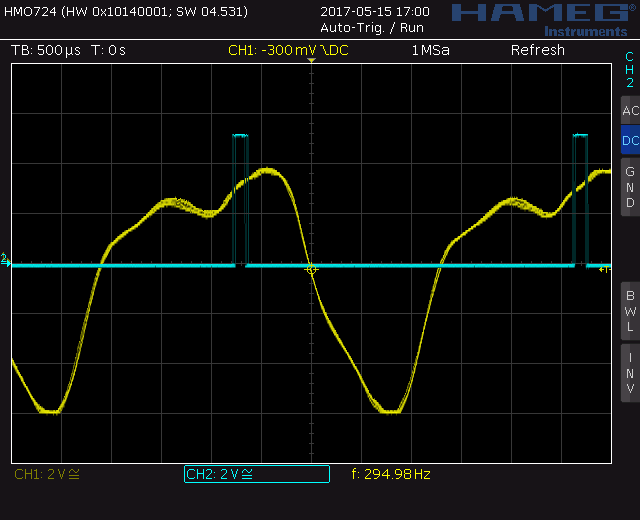
Shakuhachi 2 Synth Procect: Shakuhachi signal Ro otsu
First stage if the filter is 36dB high pass followed by a 36dB low pass. They form a bandpass with the frequency adjusted to a 1.8 Shakuhachi. The filter is followed by a comparator and a differentiating circuit. After some level shifting we get a pulse train at the output with the same pitch as the sinusoidal input signal. The output is 5V and around 150 micro seconds.
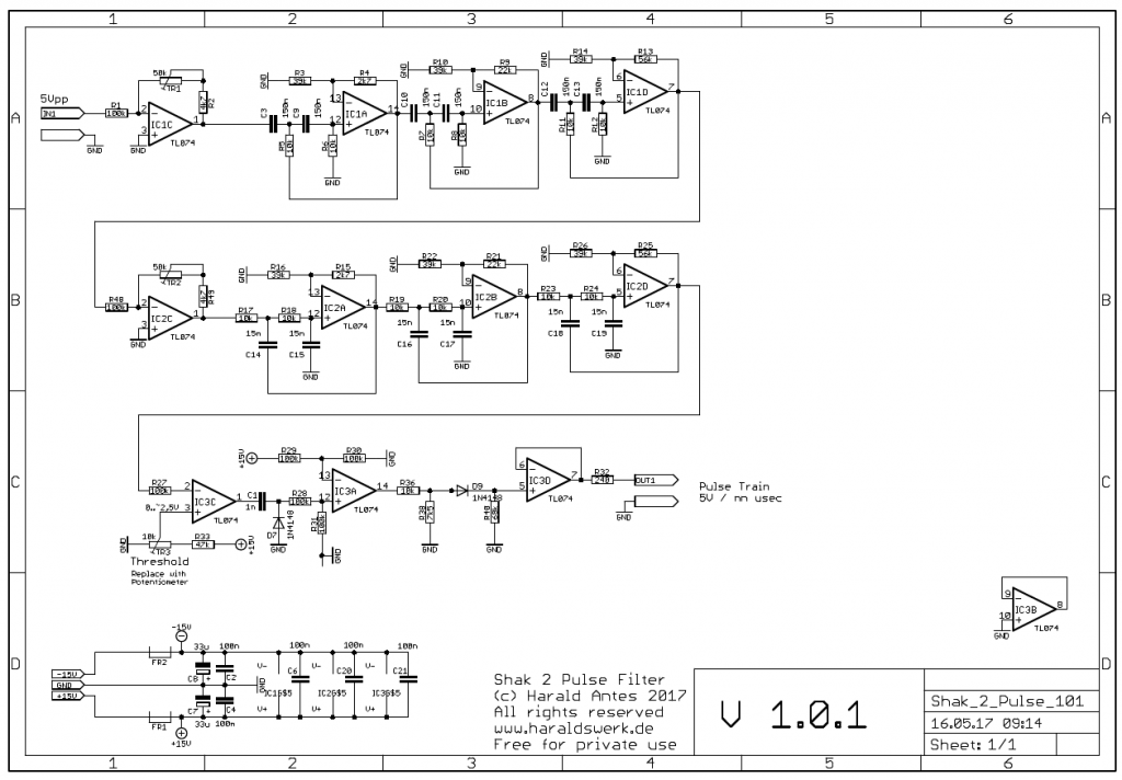
Shakuhachi 2 Synth Project: Shakuhachi 2 pulse schematic
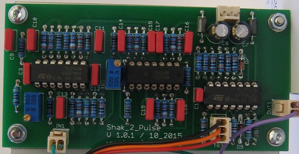
Shakuhachi 2 Synth Project: Shakuhachi 2 pulse stuffed PCB
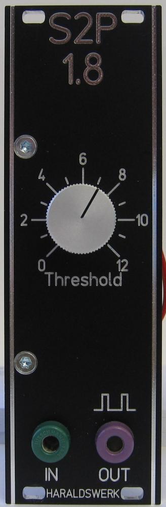
Shakuhachi 2 Synth Project: Shakuhachi 2 pulse Faceplate