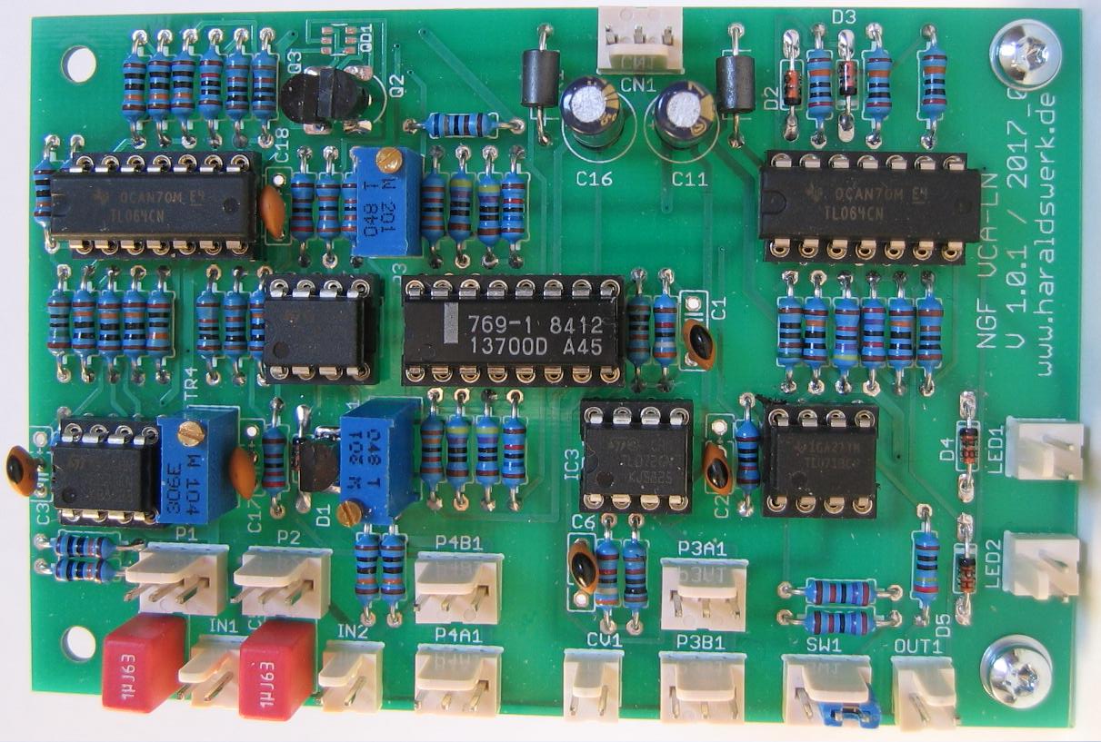
VCA LN: populated PCB
A well known way to reduce noise in VCA is using the VCA’s in parallel. Here is my approach. A LM13700 used in parallel reduces the noise floor around 3dB.
Specs and features
• VCA with reduced noise floor
• Runs on +/-15V and +/-12V (with some resistors changed)
The documentation for download can be found in my website.
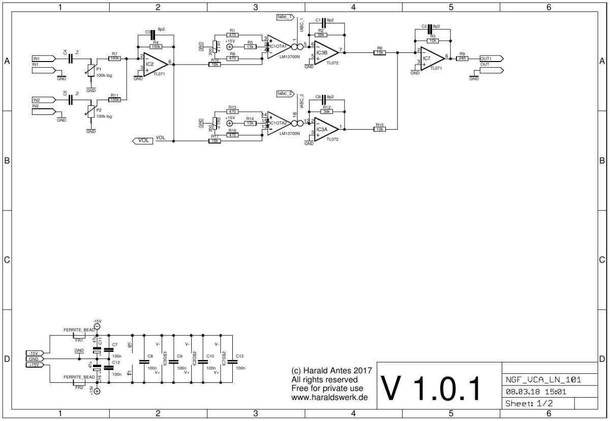
VCA LN: Schematic 01
Nothing special here. Just two plain forward designed VCA with LM13700. With the signals added together.
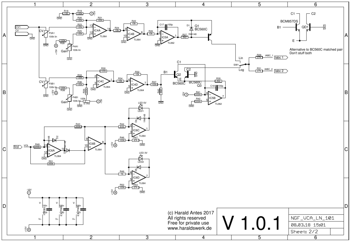
VCA LN: Schematic 02
Standard circuitry for Iabc and level control.