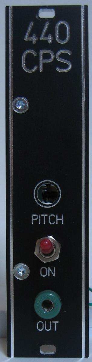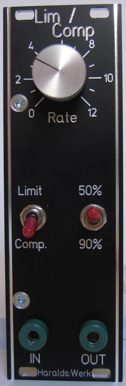
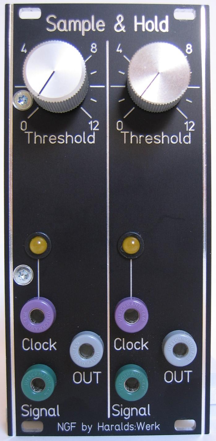
Dual Sample and Hold: front view
Storing analog signals is a often used function in analog synthesizers. This sample and hold implementation follows closely the original Elektor Formant version of Book 2 “Formant Erweiterungen” p84ff. It is build for my Next Generation Formant project. Because I use the LM13700 here as replacement for the CA3080 I have build a dual sample and hold version. The PCB size is reduced from 100x160mm for a single version to 50x70mm for the dual version.
Specs and features
• Dual sample and hold
• 10Vpp input and output
• Runs on +/-15V and +/-12V
• Power consumption below 25mA each rail
The documentation for download can be found in my website.
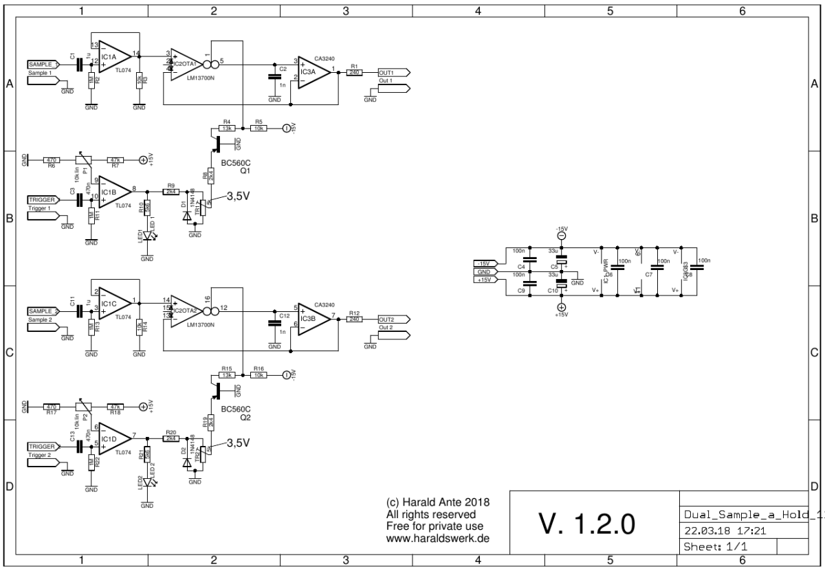
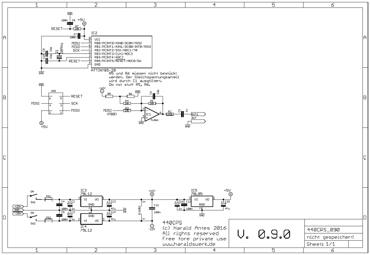
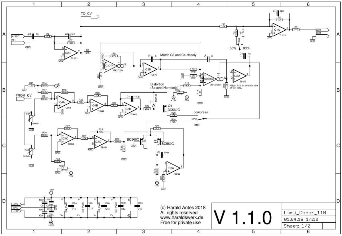
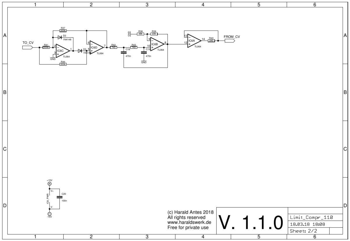
Dual Sample and Hold: schematic
This implementation follows closely the original Elektor Formant implementation. Refer to the original documentation if needed. You can find it on the net. My changes are the input buffers, using the LM13700 instead of the CA3080 and the adaption to my 10Vpp signal level.
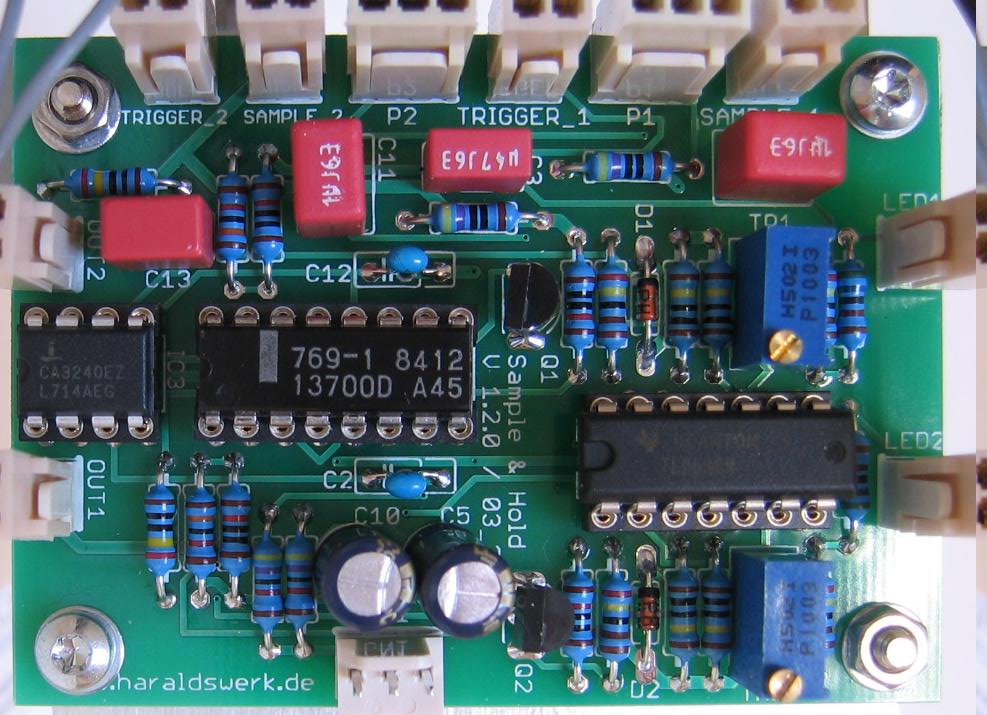
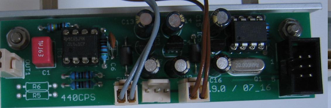
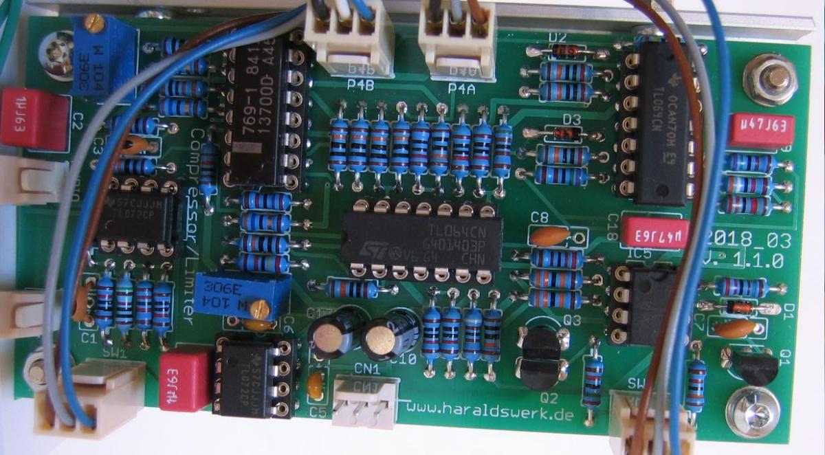
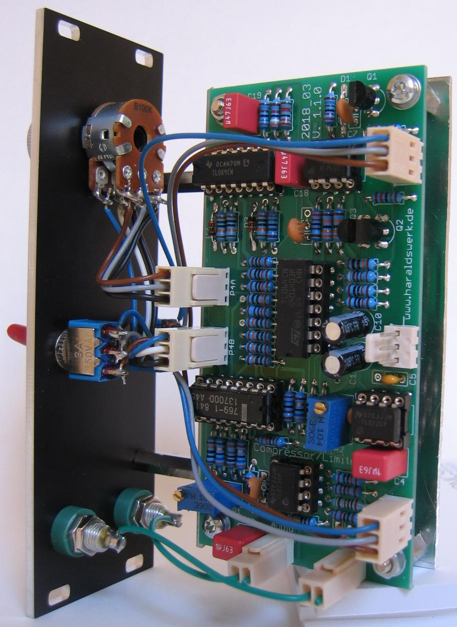
Dual Sample and Hold: populated PCB
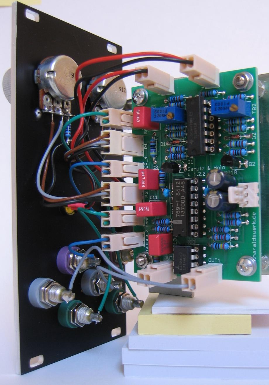
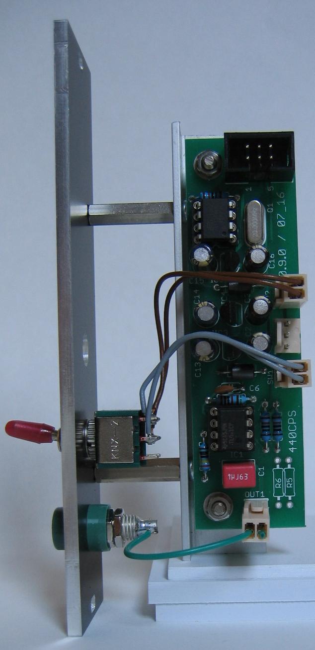
Dual Sample and Hold: back view